3 SYNCHRONISATION OF CURRENT SIGNALS
To ensure accuracy of the calculation of the differential current, the locally derived current values and the values
derived from inputs at remote terminals must be aligned to a common time reference before the differential
calculations are made. This process is called ‘Time Alignment’ or ‘Synchronisation’
Synchronism could be achieved by using accurate time signals from sources such as atomic clocks or the Global
Positioning Satellite (GPS) system. This product can synchronise using a GPS input, and this is recommended for
schemes using communications that may be subject to switching. For many applications, however, this is not
necessary, and the product can self-synchronise using a technique known as “ping-pong”.
3.1
TIME ALIGNMENT USING PING-PONG TECHNIQUE
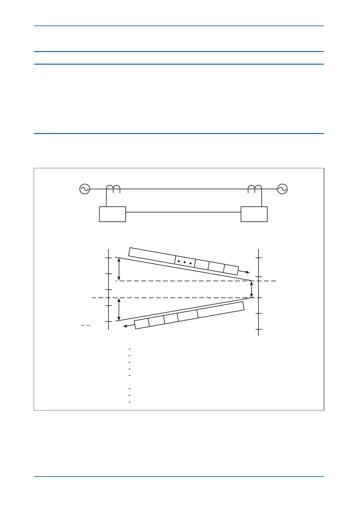
The following figure demonstrates the ping-pong technique for a two-terminal protection scheme. the two
terminals are referred to as “End A” and “End B”.
E02606
sampling instants of relay A
sampling instants of relay B
Propagation delay time from relay A to B
Propagation delay time from relay B to A
time between the arrival of message tA1
at relay B and despatch of message tB3
arrival time of message tA1 at relay B
the measured sampling time of tB3 by relay A
Measure sampling time
tB3* = (tA - tp2)
Propagation delay time
tp1 = tp2 = 1/2 (tA* - tA1 - td)
Digital communications link
Current vec
t
ors
Current vectors
tA1, tA2
tB1, tB2
tp1
tp2
tA*
tB*
tB3*
td
End A End B
A
B
tp2
tp1
td
tA1
tA2
tA3
tB3*
tA*
tA4
tA5
tB1
tB2
tB3
tB4
tB5
tB*
tA1
tA1
td
tB3
X X
Protected line
Figure 34: Ping-pong measurement for alignment of current signals
The device at End A samples its current signals at times tA1, tA2, etc. The device at End B samples its current
signals at time tB1, tB2, etc. The sampling of the signals at the two ends are not synchronised, but both operate in
the same way. The filtering and processing of the current inputs produces current vectors together with timing
information, which are sent between devices as shown in the figure.
Chapter 6 - Current Differential Protection P543i/P545i
102 P54x1i-TM-EN-1

 Loading...


