Note:
The faulted phase current (I) is generally used as the reference (0º) for the vector diagrams.
3.1 MHO CHARACTERISTICS
There are different types of Mho characteristic, but two specific ones are well suited to introducing the defining
principles. These are the directional Self-polarized Mho and the Offset Mho. Both types are used for both phase
faults and earth faults.
In practice, self-polarized Mhos are rarely used since voltage collapses for close-up faults render self-polarization
unreliable. Rather, memory-polarization components and/or cross-polarization components are usually used to
provide a polarizing reference. Directional Self-Polarized Mhos, however, are simpler to understand and are used
by way of introduction.
3.1.1
DIRECTIONAL MHO CHARACTERISTIC FOR PHASE FAULTS
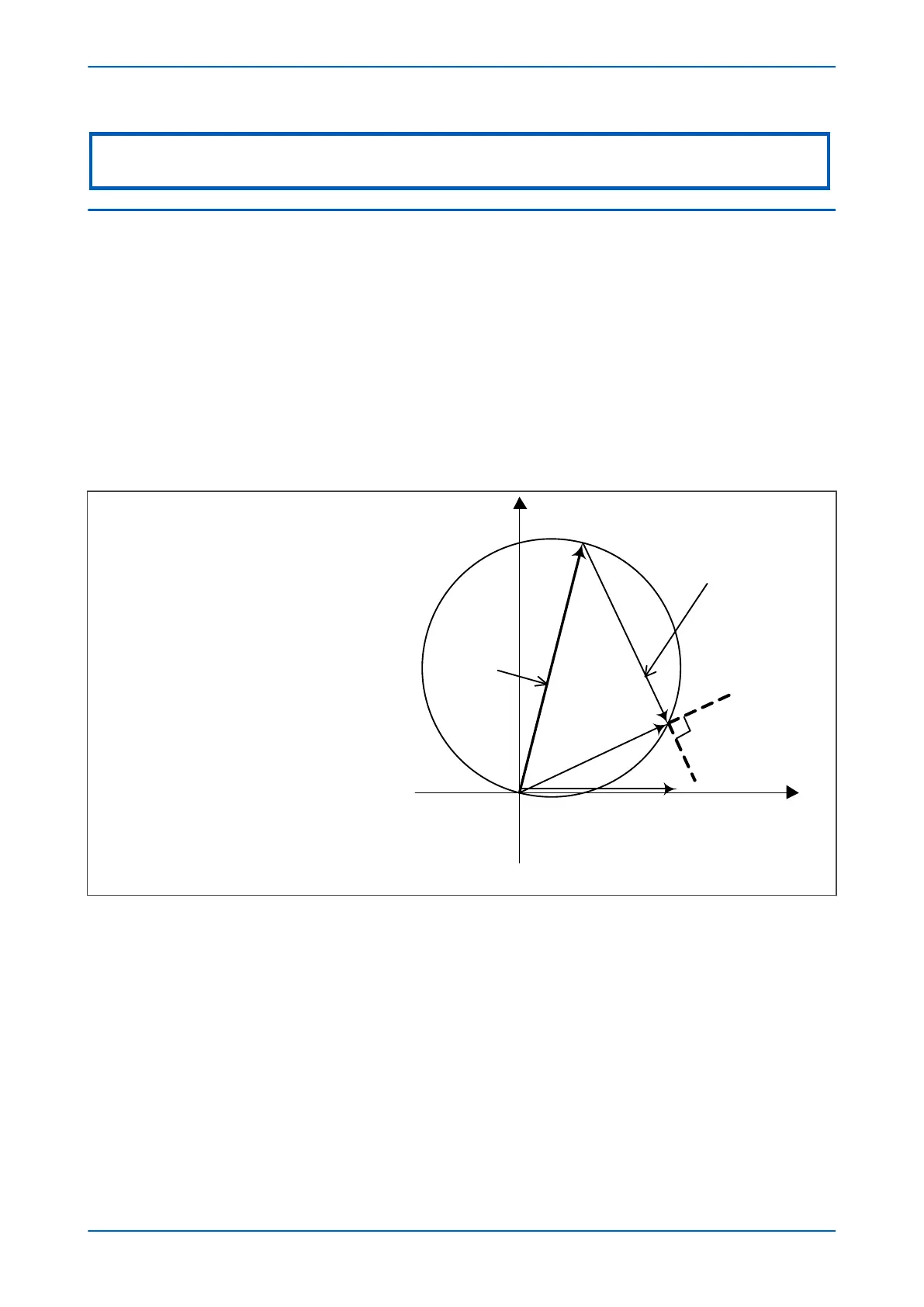
The following diagram illustrates how the Directional Self-Polarized Mho characteristic for phase Distance
protection is created.
Figure 51: Directional mho element construction
The two signals provided to the comparator are:
S
1
= V
S
2
= V - I.Z
Operation occurs when the angle between the signals is greater than 90°
3.1.2
OFFSET MHO CHARACTERISTIC FOR PHASE FAULTS
The following diagram illustrates how the Offset Mho characteristic for phase Distance protection is created:
P543i/P545i Chapter 7 - Distance Protection
P54x1i-TM-EN-1 139

 Loading...


