4 FRONT PANEL
4.1 FRONT PANEL
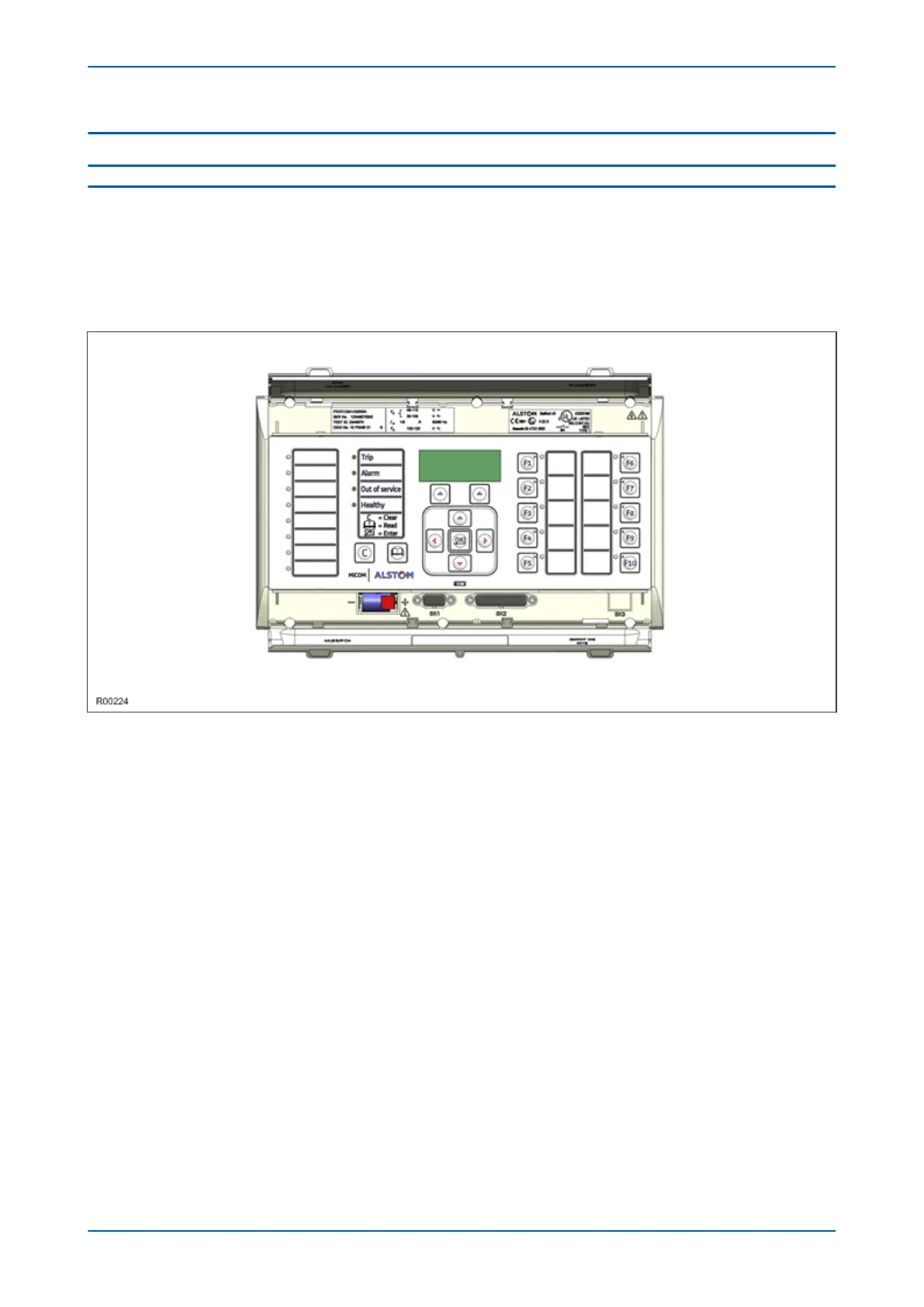
Depending on the exact model and chosen options, the product will be housed in either a 40TE, 60TE or 80TE case.
By way of example, the following diagram shows the front panel of a typical 60TE unit. The front panels of the
products based on 40TE and 80TE cases have a lot of commonality and differ only in the number of hotkeys and
user-programmable LEDs. The hinged covers at the top and bottom of the front panel are shown open. An optional
transparent front cover physically protects the front panel.
Figure 7: Front panel (60TE)
The front panel consists of:
● Top and bottom compartments with hinged cover
● LCD display
● Keypad
● 9 pin D-type serial port
● 25 pin D-type parallel port
● Fixed function LEDs
● Function keys and LEDs (60TE and 80TE models)
● Programmable LEDs (60TE and 80TE models)
4.1.1
FRONT PANEL COMPARTMENTS
The top compartment contains labels for the:
● Serial number
● Current and voltage ratings.
P543i/P545i Chapter 3 - Hardware Design
P54x1i-TM-EN-1 37

 Loading...


