6.4 POWER SUPPLY BOARD
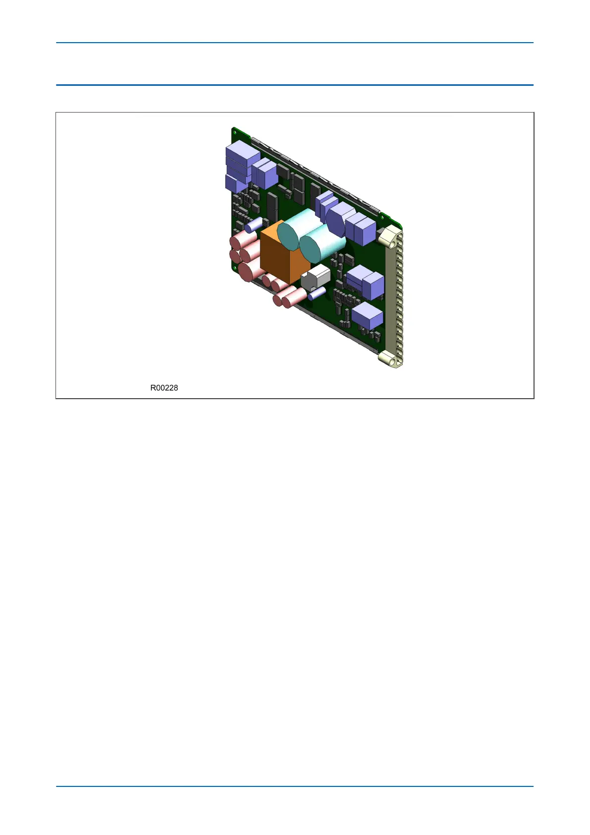
Figure 12: Power supply board
The power supply board provides power to the unit. One of three different configurations of the power supply
board can be fitted to the unit. This is specified at the time of order and depends on the magnitude of the supply
voltage that will be connected to it.
There are three board types, which support the following voltage ranges:
● 24/54 V DC
● 48/125 V DC or 40-100V AC
● 110/250 V DC or 100-240V AC
The power supply board connector plugs into a medium duty terminal block. This terminal block is always
positioned on the right hand side of the unit looking from the rear.
The power supply board is usually assembled together with a relay output board to form a complete subassembly,
as shown in the following diagram.
P543i/P545i Chapter 3 - Hardware Design
P54x1i-TM-EN-1 45

 Loading...


