V02500
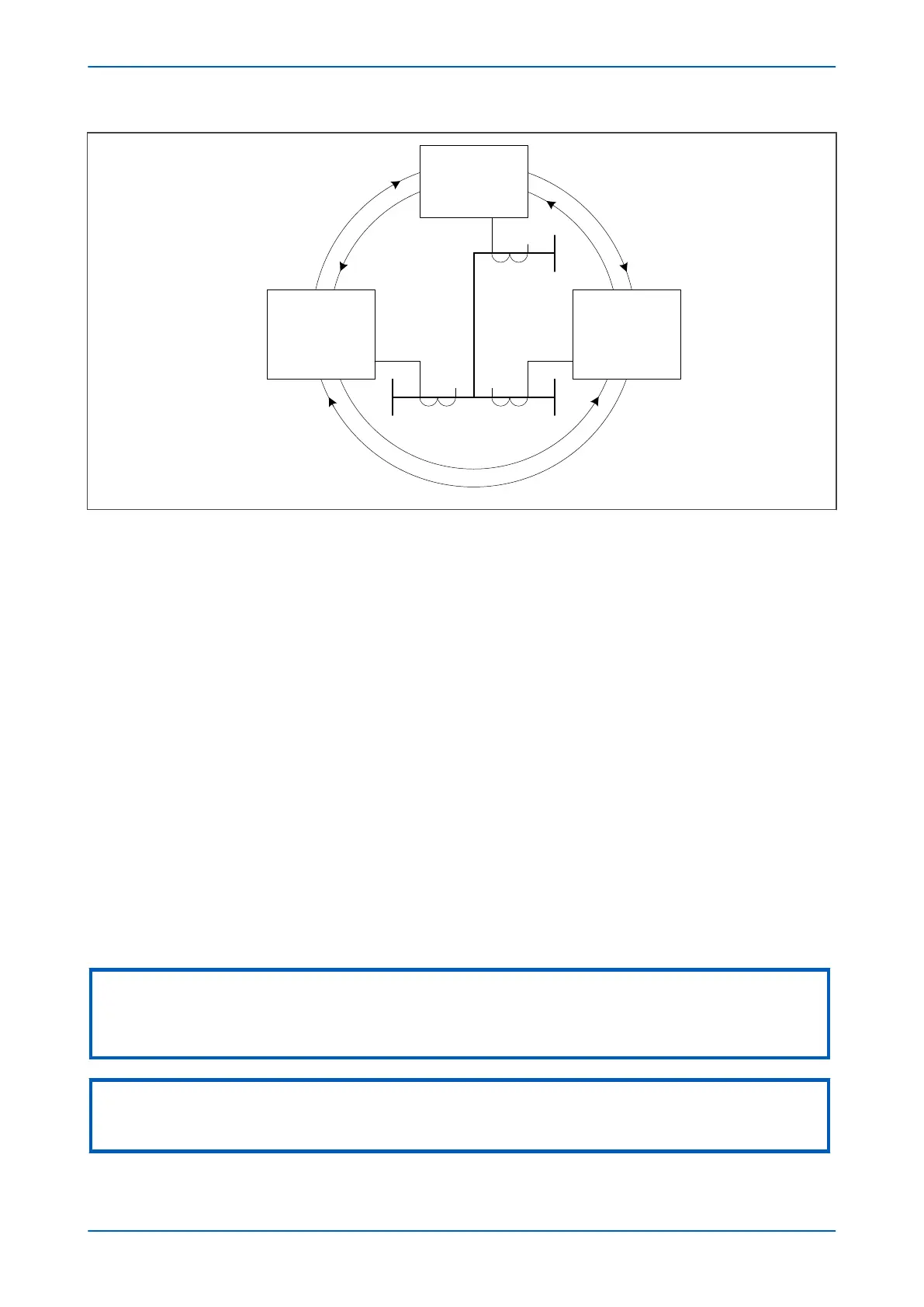
Local
IED B
Ch1 Ch2
IED C
Ch1
Ch2
IED A
Ch1
Ch2
Rx
RxTx
Rx
Tx
Tx
Rx Tx TxRx
RxTx
Remote 1
Remote 2
Figure 273: Fibre Teleprotection connections for a three-terminal Scheme
3.1.1
FIBRE TELEPROTECTION SCHEME TERMINAL ADDRESSING
In Fibre Teleprotection schemes, commands are packaged together with other important data for transmission
over communications channels to the other devices. The packages of information are generally called ‘messages’.
These messages are created for a specific destination where they will be acted upon to realise the overall scheme
protection. It is critical that they are only used by the intended device. Making the correct channel connections
may not always ensure that the messages get to the correct destination; there may be a possibility that
communication paths may become cross-connected or looped back during telecommunications network
switching operations. To avoid incorrect scheme operation, extra security is needed to ensure that messages are
acted upon only by their intended recipient. This is achieved by means of an address field in the messages. The
address field is used to individually match connected devices. A transmitting device includes the address of the
intended recipient in the message. If the receiving device matches the address, the message will be used. If it does
not match, it is discarded.
The address field is an 8-bit field in the message. It can carry any 8-bit value, but certain values have been chosen
for maximum security. For convenience they have been arranged into 32 groups. All devices in a scheme must
share the same group. For addressing, the different devices are referenced as ‘A’, ‘B’, and ‘C’ for three-terminal
schemes. Their addresses should recognise the referencing.
So for a two-terminal scheme, if one device has the address set to ‘5-A’ the other should have the address to ‘5-B’.
Similarly, in a three-terminal scheme if one device has address ‘1-A’, the other devices would have addresses ‘1-B’
and ‘1-C’. The address is set using the address setting in the PROT COMMS/IM64 column.
Note:
A universal address (0-0) is used as default. If this is used all products use the same address ‘0-0’. This is primarily intended to
help test the product before it goes into service. We strongly recommend not to use 0-0 in service since any communications
switching or loopback condition will not be detected and may cause false tripping.
Note:
For a three-terminal scheme, the A, B, and C parts of the address group should match the figure shown earlier for a
triangulated scheme where device A has address A, device B has address B, and device C has address C.
P543i/P545i Chapter 20 - Fibre Teleprotection
P54x1i-TM-EN-1 503

 Loading...


