V01216
52A
52B
Output Relay
+ve
-ve
Opto-input
Circuit Breaker
R3
R2
R1
Trip path
Trip coil
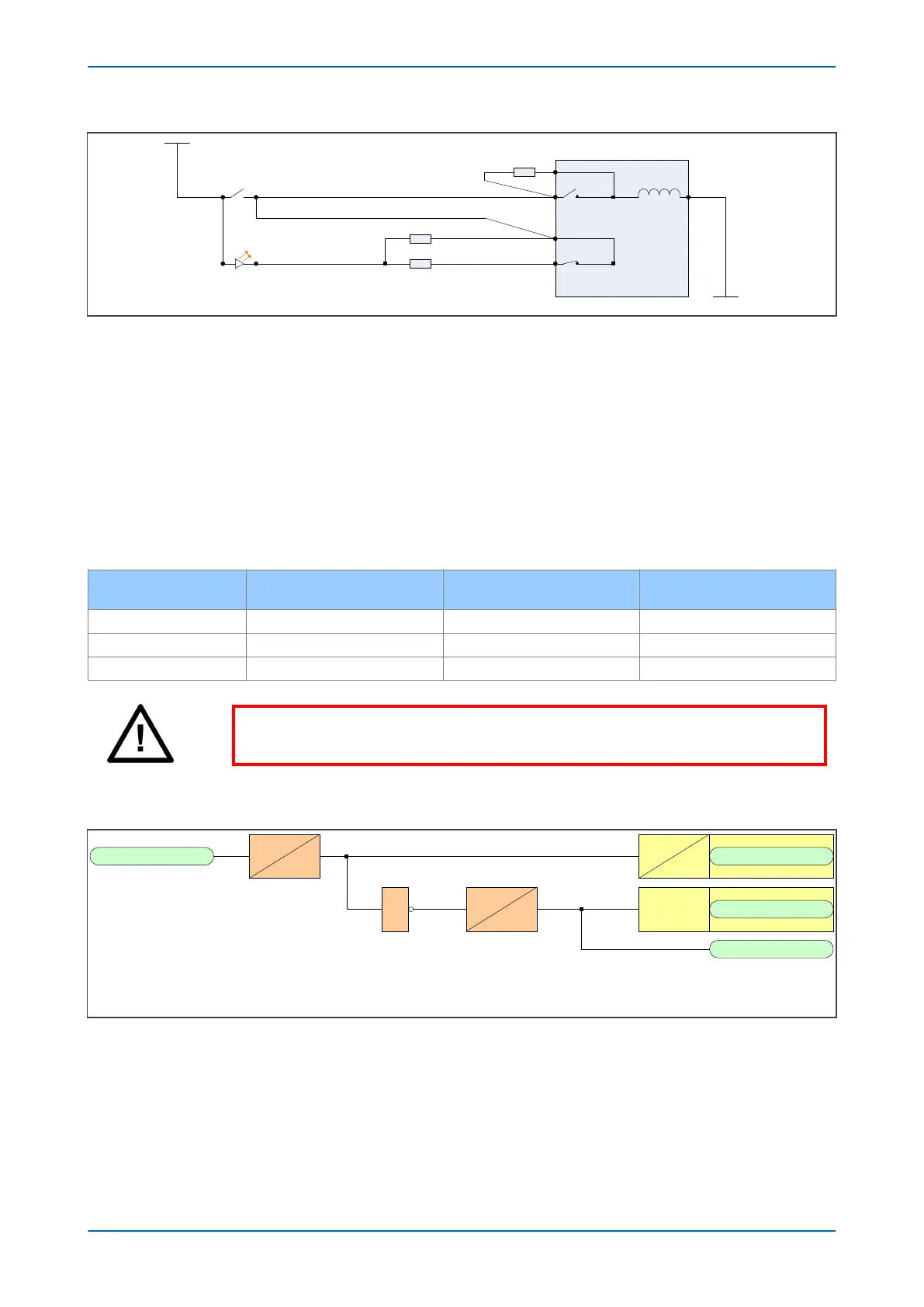
Figure 269: TCS Scheme 3
When the CB is closed, supervision current passes through the opto-input, resistor R2 and the trip coil. When the
CB is open, current flows through the opto-input, resistors R1 and R2 (in parallel), resistor R3 and the trip coil. The
supervision current is maintained through the trip path with the breaker in either state, therefore providing pre-
closing supervision.
5.3.1
RESISTOR VALUES
Resistors R1 and R2 are used to prevent false tripping, if the opto-input is accidentally shorted. However, unlike the
other two schemes. This scheme is dependent upon the position and value of these resistors. Removing them
would result in incomplete trip circuit monitoring. The table below shows the resistor values and voltage settings
required for satisfactory operation.
Trip Circuit Voltage
Opto Voltage Setting with R1
Fitted
Resistor R1 & R2 (ohms) Resistor R3 (ohms)
48/54 24/27 1.2k 600
110/250 48/54 2.7k 1.2k
220/250 110/125 5.0k 2.5k
Warning:
This Scheme is not compatible with Trip Circuit voltages of less than 48 V.
5.3.2 PSL FOR TCS SCHEME 3
Opto Input
V01217
&
*Output Relay
LED
User Alarm
pickup
0
50
0
400
dropoff
Straight
0
0
Latching
*NC stands for Normally Closed.
Figure 270: PSL for TCS Scheme 3
Chapter 18 - Supervision P543i/P545i
482 P54x1i-TM-EN-1

 Loading...


