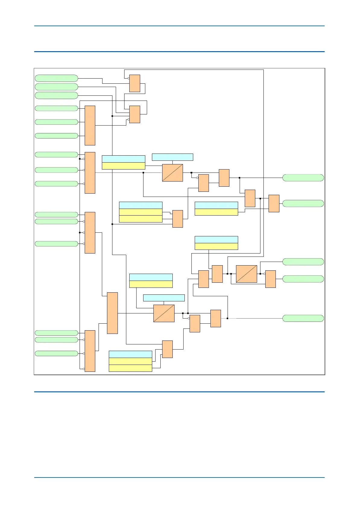
4.2 DIFFERENTIAL CTS LOGIC
CT1 L i1>
CT1 R1 i1>
CT1 R2 i1>
>
=
2
CT1 R1 i2/i1>
CT1 R2 i2/i1>
&
CT1 L i2/i1>>
CT1 R2 i2/i1>
CT1 R1 i2/i1 >>
CT1 L i2/i1>
CT1 R1 i2/i1>
CT1 R2 i2/i1 >>
CT1 L i2/i1>
&
&
1
Disable CTS
Any Trip
Inhibit CTS
&
CTS Block
CT Fail Alarm
V01262
1
CTS Time Delay
Pickup
*In indication mode , timer is set to 20ms
S
R
Q
&
1
&
CTS Reset Mode
Manual
Auto
CTS Status
Restrain
CTS Status
Indication
1
CTS Time Delay
Pickup
S
R
Q
&
CTS Reset Mode
Manual
Auto
Pickup
&
&
CTS Status
Restrain
1
1
CTS Block Diff
CTS Restrain
Remote CT Alarm
CTS Status
Indication
*
Figure 263: Differential CTS
4.3
CTS IMPLEMENTATION
If the power system currents are healthy, no zero sequence voltage are derived. However, if one or more of the AC
current inputs are missing, a zero sequence current would be derived, even if the actual power system phase
currents are healthy. Standard CTS works by detecting a derived zero sequence current where there is no
corresponding derived zero sequence voltage.
The voltage transformer connection used must be able to refer zero sequence voltages from the primary to the
secondary side. Therefore, this element should only be enabled where the VT is of a five-limb construction, or
comprises three single-phase units with the primary star point earthed.
Chapter 18 - Supervision P543i/P545i
476 P54x1i-TM-EN-1

 Loading...


