13 DELTA DIRECTIONAL COMPARISON
13.1 SINGLE-ENDED TESTING
If the delta directional comparison aided scheme is being used, test the operation
1. In the CONFIGURATION column, disable all protection elements other than the one being tested.
2. Make a note of which elements need to be re-enabled after testing
13.1.1 PRELIMINARIES
Use a three-phase digital/electronic injection test set to make the commissioning procedure easier.
Connect the test equipment to the device using the test block(s) taking care not to open-circuit any CT secondary.
If MMLG type test blocks are used, the live side of the test plug must be provided with shorting links before it is
inserted into the test block.
13.1.2
SINGLE-ENDED INJECTION TEST
This set of injection tests aims to determine correct operation of a single IED at one end of the scheme. The device
is tested in isolation, with the communications channel to the remote line terminal disconnected.
First verify that the device cannot send or receive channel scheme signals to or from the remote line end.
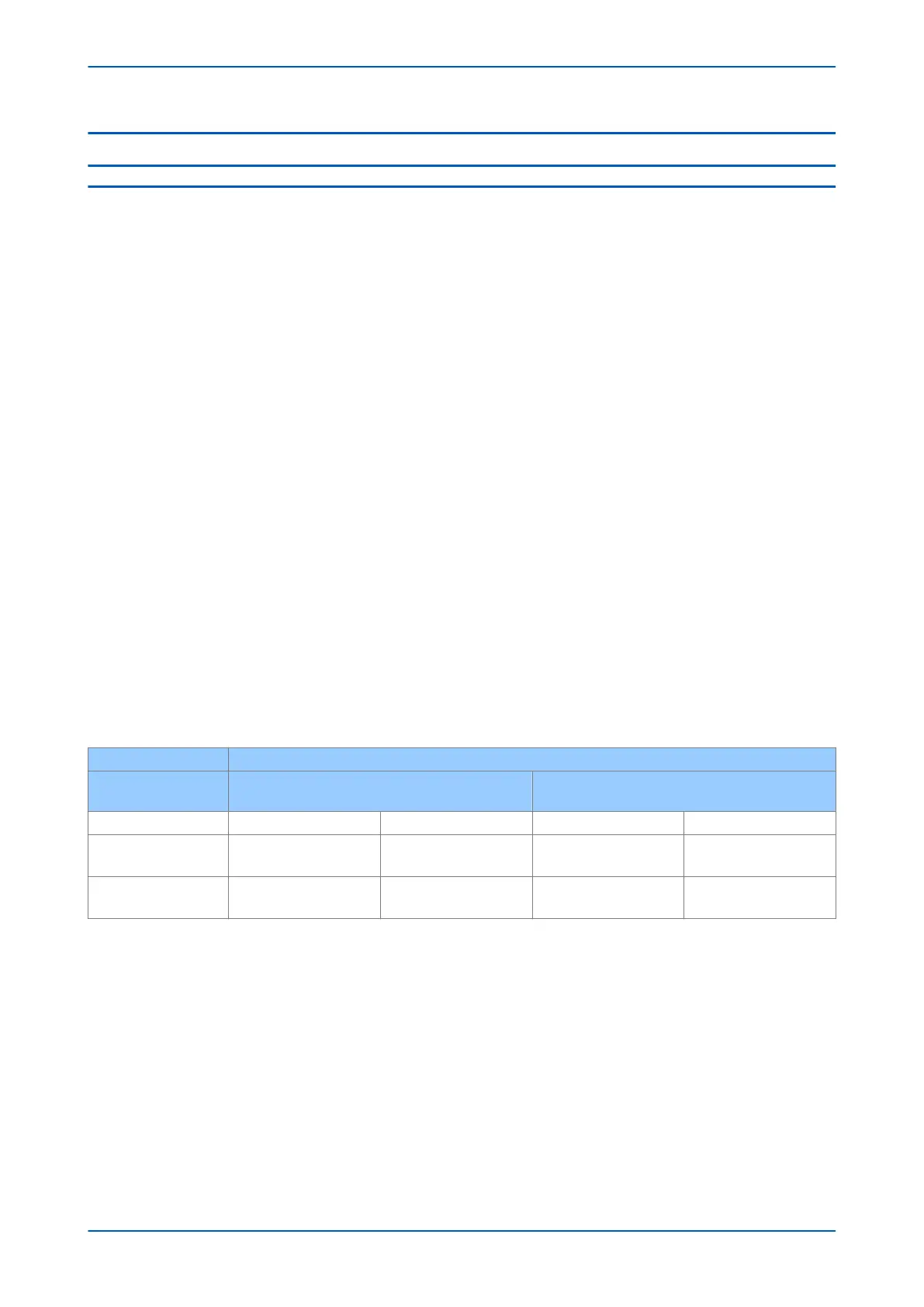
The device is tested for its response to forward and reverse fault injections, but the response depends on the aided
channel (pilot) scheme that is selected. The table below shows the expected response for various test situations for
a conventional signalling scheme.
We assume a conventional signalling scheme implementation.
If an InterMiCOM
64
scheme is used to provide the signalling, the scheme logic may not use opto-inputs for the
aided scheme implementation. In this case, internal DDB signals need to be set or reset to test the operation of the
protection scheme.
Use the IM64 Test Mode with the IM64 Test Pattern to assert or monitor the relevant signals.
IED RESPONSE
Direction of fault test
injection
Forward fault Reverse fault
Signal receive opto ON OFF ON OFF
Blocking scheme
No Trip,
No Signal Send
Trip,
No Signal Send
No Trip,
Signal Send
No Trip,
Signal Send
Permissive scheme (POR/
POTT)
Trip,
Signal Send
No Trip,
Signal Send
No Trip,
No Signal Send
No Trip,
No Signal Send
13.1.3 FORWARD FAULT PREPARATION
Configure the test set to inject a dynamic sequence of injection, as follows:
1. Simulate a healthy three-phase set of balanced voltages, each of magnitude Vn. No load current should be
simulated. The duration of injection should be set to 1 second. Step 1 therefore mimics a healthy unloaded
line before the onset of a fault.
2. Simulate a forward fault on the A-phase. The A-phase voltage must be simulated to drop by 3 times the Dir.
V Fwd setting,
Va = Vn – 3 (Dir. V Fwd)
The fault current on the A-phase should be set to 3 times the Dir. I Fwd setting, lagging Va by a phase angle equal
to the line angle,
Chapter 25 - Commissioning Instructions P543i/P545i
674 P54x1i-TM-EN-1

 Loading...


