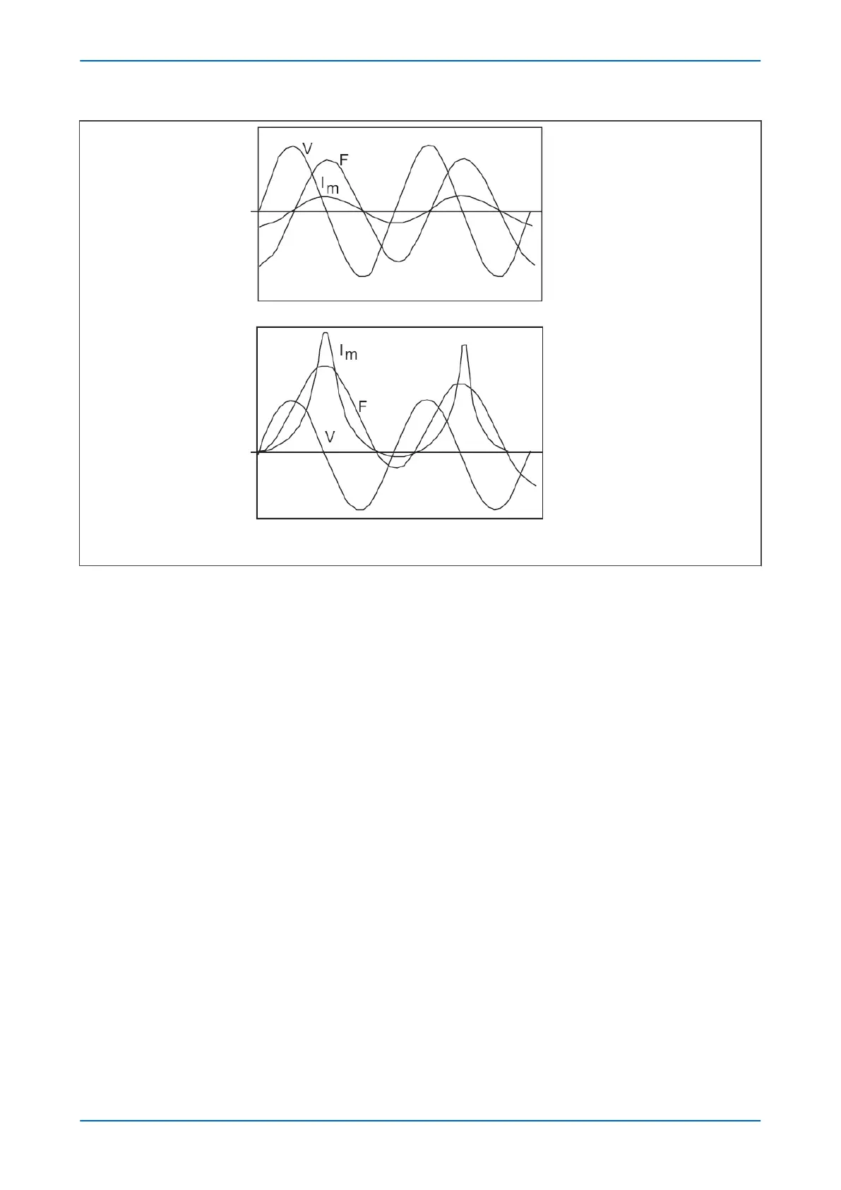
Steady state
Switch on at voltage
zero – No residual flux
+F
m
-F
m
2F
m
V03123
V = Voltage, F = Flux, Im = magnetising current, Fm = maximum flux
Figure 41: Magnetising inrush phenomenon
The main characteristics of magnetising inrush currents are:
● Higher magnitude than the transformer rated current magnitude
● Containing harmonics and DC offset
● Much longer time constant than that of the DC offset component of fault current
We can see that inrush current is a regularly occurring phenomenon and should not be considered a fault, as we
do not wish the protection device to issue a trip command whenever a transformer is switched on at an
inconvenient point during the input voltage cycle. This presents a problem to the protection device, because it
should always trip on an internal fault. The problem is that typical internal transformer faults may produce
overcurrents which are not necessarily greater than the inrush current. Furthermore, faults tend to manifest
themselves on switch on, due to the high inrush currents. For this reason, we need to find a mechanism that can
distinguish between fault current and inrush current. Fortunately, this is possible due to the different natures of the
respective currents. An inrush current waveform is rich in harmonics, especially 2nd harmonics, whereas an
internal fault current consists only of the fundamental. We can therefore develop a restraining method based on
the 2nd harmonic content of the inrush current. The mechanism by which this is achieved, is called second
harmonic blocking.
10.3.1
SECOND HARMONIC RESTRAINT
When set to protect feeders with in-zone transformers, this product measures the second harmonic components
of the input currents to detect magnetising inrush, which can be used to modify operation of the current
differential protection.
P543i/P545i Chapter 6 - Current Differential Protection
P54x1i-TM-EN-1 117

 Loading...


