These settings will give a characteristic suitable for most applications. It leaves only the Phase Is1 setting to be
decided by you. The value of this setting should be in excess of any mismatch between line ends. It should also
account for line charging current, where necessary.
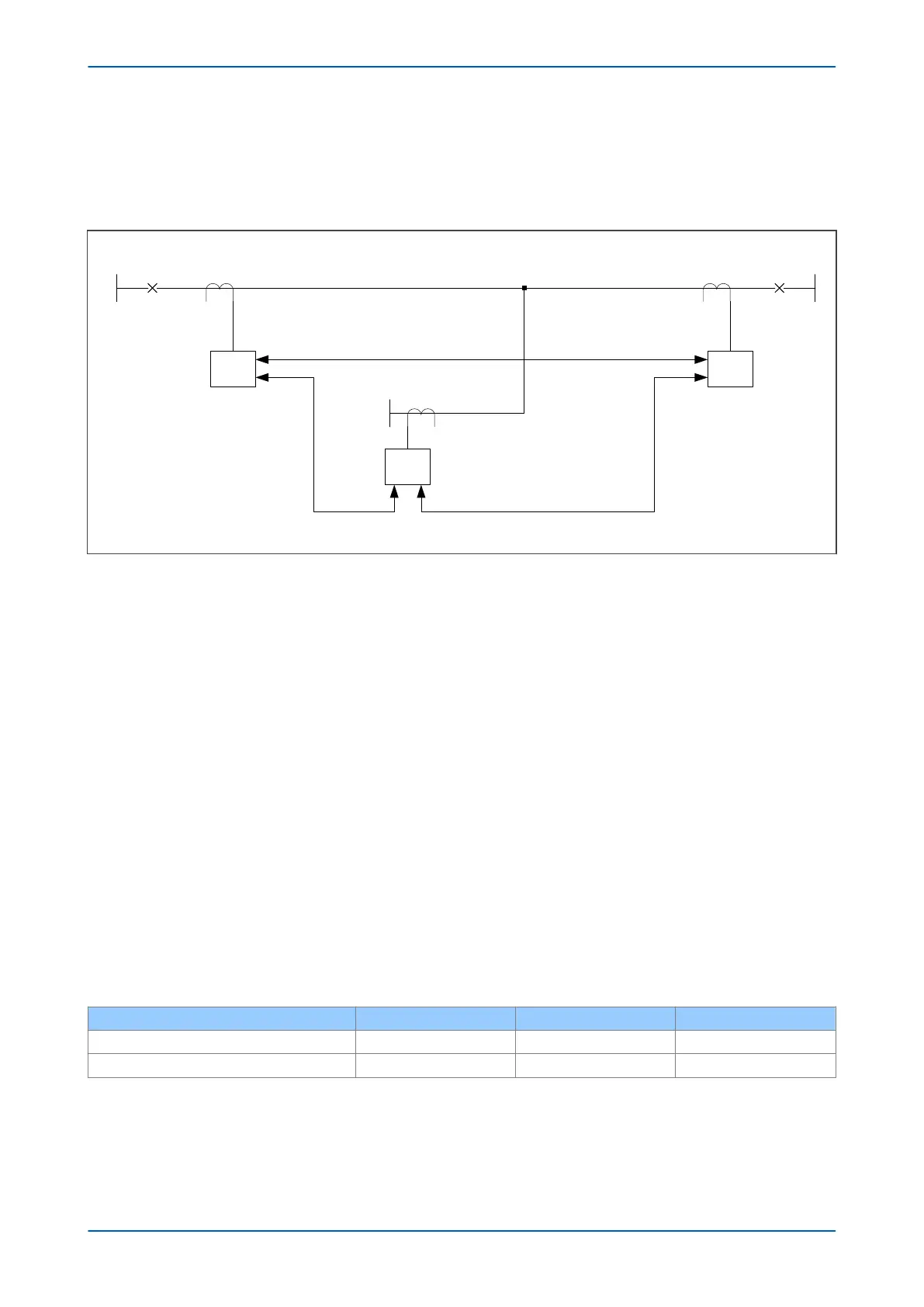
By considering the circuit shown below, the settings for the phase current differential element can be established.
P54x
V02620
P54x
Digital communication link
Protected line
275 kV 275 kV
400/5400/5
45 km
End A End B
30 km
Ch 1
Ch 2
P54x
10 km
275 kV
End C
Ch 2
Ch 1 Ch 2
Ch 1
Steady state charging current = 0.58 A/km - overhead line
Digital communication link Digital communication link
1200/5
Figure 49: Typical three-terminal plain feeder circuit
If there are no VT inputs connected, the setting Phase Is1 must be 2.5 times the steady state charging current
suitably corrected for the different CT ratios as presented below in the calculation of charging current
compensated values. For an overhead line circuit with a charging current of 0.58A/km the charging current will be:
Ich = 0.58 A ( 45 + 30 + 10 ) = 49.3 A
If VT inputs are connected, there is a facility to overcome the effect of charging current. To do this you need to
enter the positive sequence capacitive susceptance value.
Considering the charging current on the circuit shown in the figure above, the following calculation applies:
Ich = 0.58 A ( 45 + 30 + 10 ) = 49.3 A
Susceptance =
w
C = Ich/V
B = 49.3 A/( 275/
Ö
3) kV primary
B = 0.31 x 10⁻³ S primary.
The CT ratios on the three ends are different, so it is necessary to apply a correction factor to ensure secondary
currents balance for all conditions:
To calculate the correction factor (CF), the same primary current must be used even if this current is not the
expected load transfer for every branch. This will ensure secondary current balance for all conditions.
CT ratio correction input data is shown in the table below:
Setting
End A End B End C
Phase CT Primary 4000A 4000A 1200A
Ph CT Corr’tion 4000/1200 = 3.33 4000/1200 = 3.33 1 (reference)
We recommend the following settings:
Phase Is1 = 0.2 p.u. = 0.2*1200A = 240A
Phase Is2 = 2 p.u. = 2*1200A = 2400A
Chapter 6 - Current Differential Protection P543i/P545i
130 P54x1i-TM-EN-1

 Loading...


