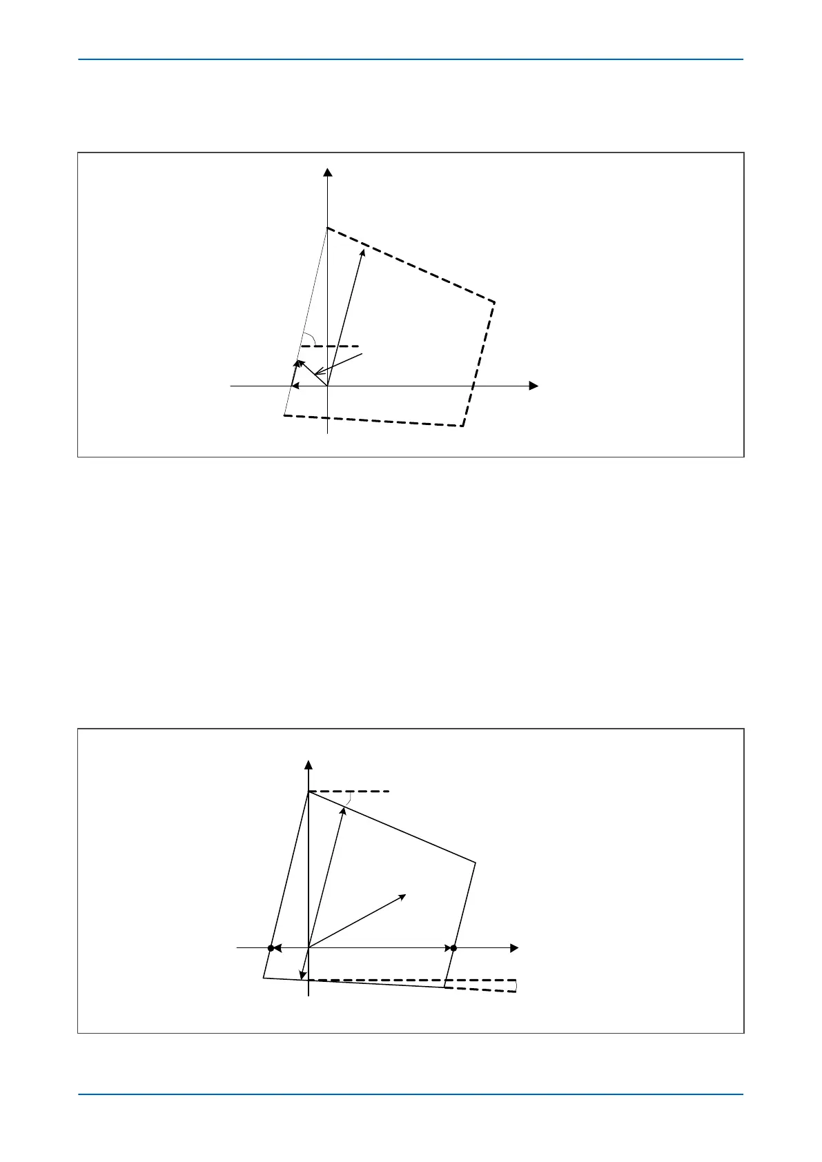
3.3.4 PHASE FAULT REVERSE RESISTIVE REACH LINE
+R
+jX
V02726
Z
V / I - R’
V / I
R’
Ð
Z
Figure 75: Reverse resistive reach line construction
For an offset zone, R’ is the settable reverse resistive reach (=½*Rx’ Ph Res. Rev.). . For a directional zone, R’ is fixed
at 25% of the Resistive Reach (=½*Rx Ph Res. Rev.), acting in the opposite direction.
The two signals provided to the comparator are:
S
1
= V - I.R
S
2
= I.Z
The impedance on the right side of the left hand resistive line is detected when the angle between S1 and S2 is less
than 0°.
3.3.5
PHASE FAULT QUADRILATERAL CHARACTERISTIC SUMMARY
The phase fault Quadrilateral characteristics are summarised in the following figure and tables:
+R
+jX
V02727
Z
V / I
R’
3°
Z’
R
Figure 76: Phase Fault Quadrilateral characteristic summary
Chapter 7 - Distance Protection P543i/P545i
166 P54x1i-TM-EN-1

 Loading...


