V02763
Zone 6
Zone 5
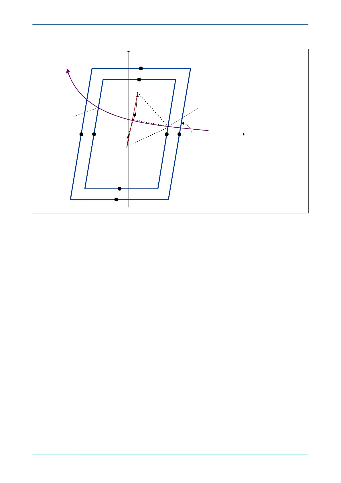
Resistive forward (+R)
Resistive reverse (R’)
α
OST Z5
OST Z6
OST Z5'
OST Z6'
OST R6OST R5
OST R5'OST R6'
+jX
Z
S
Z
L
Z
R
Z
T
OST trip
Predictive OST trip
θ
Figure 160: OST setting determination for the positive sequence resistive component OST R5
Z
T
is the total system positive sequence impedance equal to Z
S
+ Z
L
+ Z
R
, where Z
S
and Z
R
are the equivalent
positive sequence impedances at the sending and receiving ends and Z
L
is the positive sequence line impedance.
θ is the angular difference between the voltages at the sending and receiving ends beyond which no system
recovery is possible.
To determine the settings for OST, the minimum inner resistive reach of OST R5 (R5min) needs to be calculated.
The figure above shows that:
R5min = (Z
T
/2) / tan(θ/2
Next the maximum (limit value) for the outer resistive reach OST R6 (R6 max) needs to be calculated. Referring to
the figure below, point A must not overlap with the load area for the worst assumed power factor of 0.85 and the
lowest possible Z
T
angle α.
P543i/P545i Chapter 10 - Power Swing Functions
P54x1i-TM-EN-1 287

 Loading...


