Z(1+k
ZN
.I
N
/I
ph
+k
ZM
.I
M
/I
ph
)
Then if healthy phase currents are much less then the current of the faulty phase and the mutual compensation is
disabled:
I
N
@
I
ph
so that
Z
replica
@
Z(1 + k
ZN
)
Thus the Z
LP
plane representation of the characteristic becomes static.
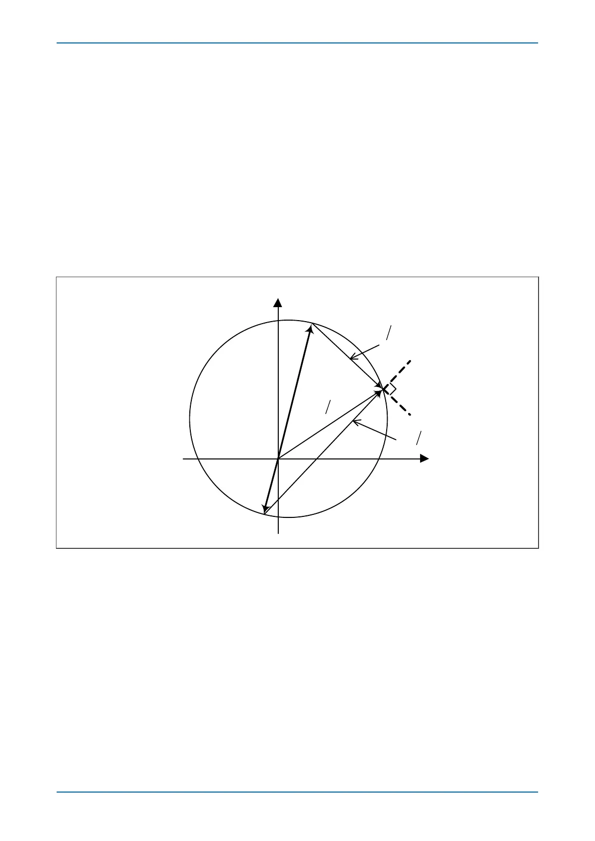
3.1.4 OFFSET MHO CHARACTERISTIC FOR EARTH FAULTS
The diagram below illustrates how the Offset Mho characteristic for earth-fault distance protection is created in
the impedance domain.
Figure 54: Offset Mho characteristics – impedance domain
The two signals provided to the comparator are:
S
1
= V - I.Z'
S
2
= V - I.Z
Operation occurs when the angle between the signals is greater than 90°.
The following diagram below how the Offset Mho characteristic for earth-fault distance protection translates to
the loop impedance domain.
Chapter 7 - Distance Protection P543i/P545i
142 P54x1i-TM-EN-1

 Loading...


