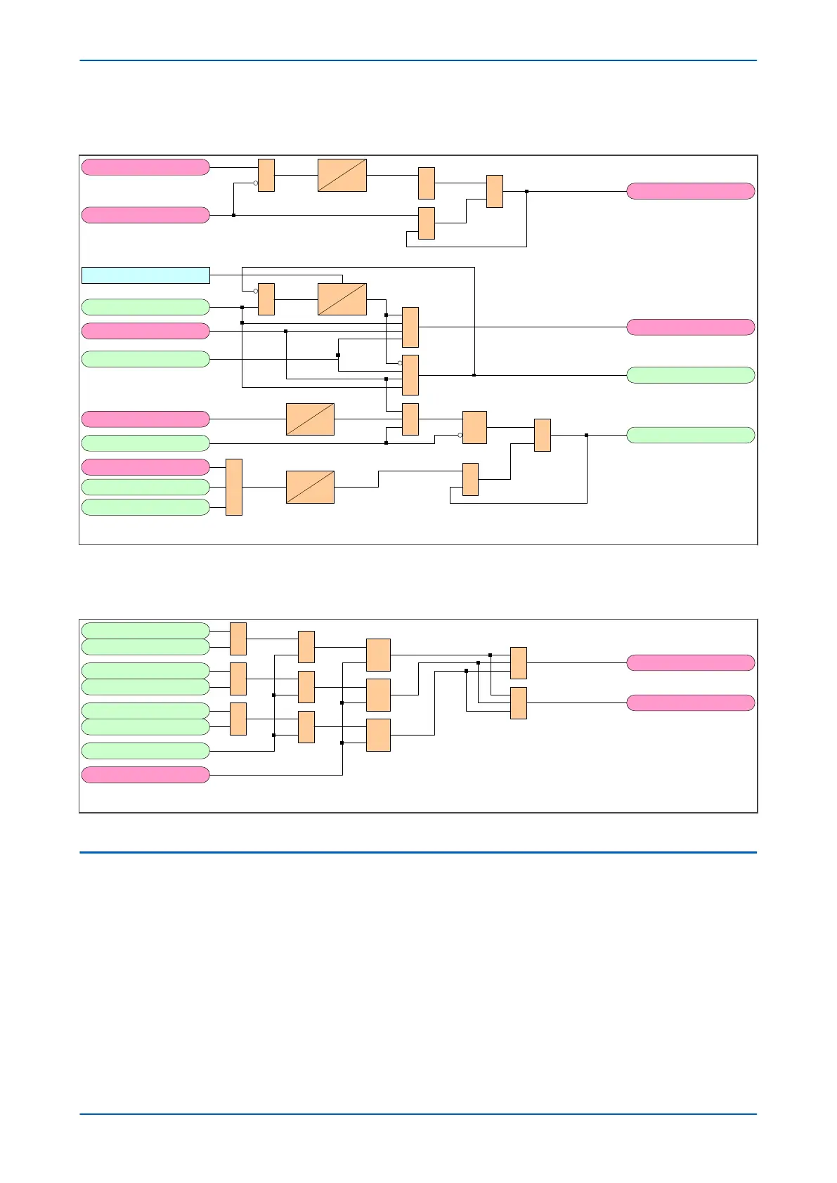
5.7.4 PROTECTION REOPERATION AND EVOLVING FAULT LOGIC DIAGRAM
V03331
TARANY
&
TMEMANY
Prot ReOp
LastShot
Set CB1 CL
1P DTime
Seq Counter = 1
A/R Lockout
CB Closed 3 ph
CB ARIP
Prot ReOp
Evolve Lock
Evolve 3Ph
CB Failed AR
&
&
1
0
0.02
&
Discrim Time
t
0
&
&
0
0.02
R
Q
S
&
&
1
0
0.02
&
Figure 182: Protection Reoperation and Evolving Fault logic diagram (Module 20)
5.7.5
FAULT MEMORY LOGIC DIAGRAM
V03320
RESPRMEM
Trip Inputs A
Ext Fault APh
FLTMEM 2P
&
FLTMEM 3P
AR Start
Trip Inputs B
Trip Inputs C
Ext Fault BPh
Ext Fault CPh
1
1
1
&
&
R
Q
S
R
Q
S
R
Q
S
=
2
&
Figure 183: Fault Memory logic diagram (Module 15)
5.8
AUTORECLOSE IN PROGRESS
The AR In Progress module produces various signals to indicate to other modules and functions that an
Autoreclose operation is currently in progress.
Chapter 11 - Autoreclose P543i/P545i
326 P54x1i-TM-EN-1

 Loading...


