Figure 16: Rear serial port terminals
An additional serial port with D-type presentation is available as an optional board, if required.
6.5
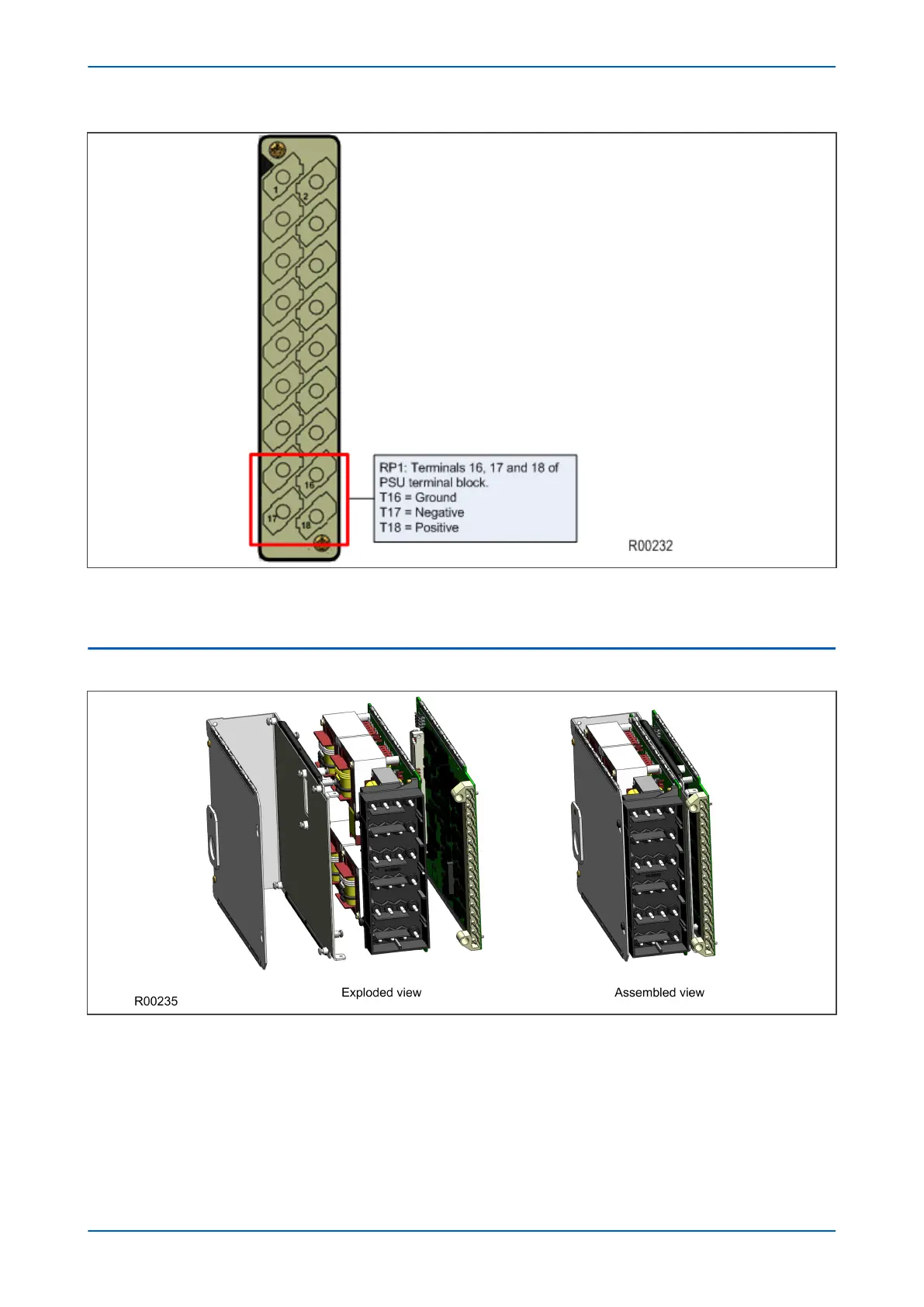
INPUT MODULE - 1 TRANSFORMER BOARD
Figure 17: Input module - 1 transformer board
The input module consists of the main input board coupled together with an instrument transformer board. The
instrument transformer board contains the voltage and current transformers, which isolate and scale the
analogue input signals delivered by the system transformers. The input board contains the A/D conversion and
digital processing circuitry, as well as eight digital isolated inputs (opto-inputs).
The boards are connected together physically and electrically. The module is encased in a metal housing for
shielding against electromagnetic interference.
P543i/P545i Chapter 3 - Hardware Design
P54x1i-TM-EN-1 49

 Loading...


