15 OUT OF STEP PROTECTION
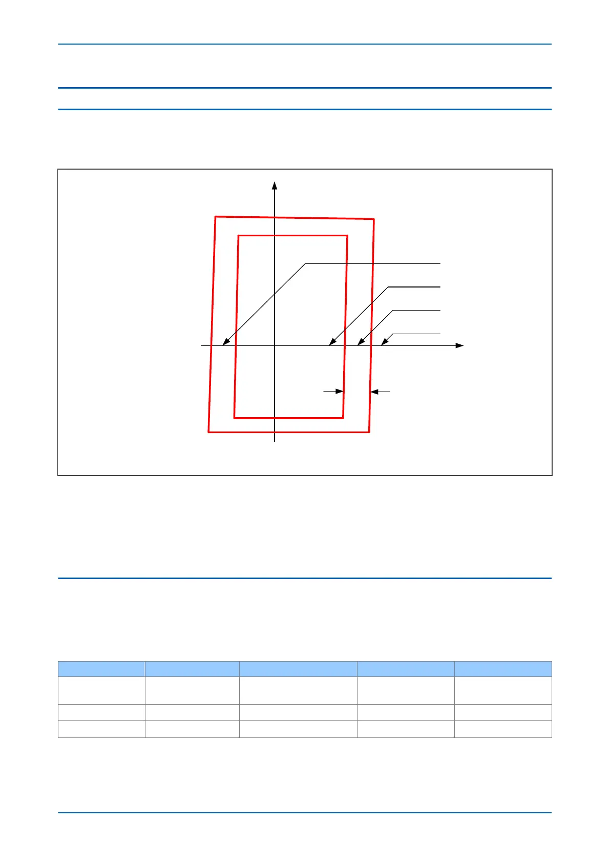
For this test, an injection set with a state sequencer function is required, as dynamic impedance conditions are
going to be tested. The four states impedances that applied during the Out of Step commissioning process are
shown below:
V01451
R
Z5
Z6
Z5'
Z6'
R5 R6R5'R6'
+jX
∆R
State 1
State 2
State 3
State 4
Figure 321: State impedances
Depending on the Out of Step (OST) settings, use one of the following setting options.
● OST setting
● Predictive OST setting
● Predictive and OST setting
15.1
OST SETTING
1. Clear all alarms.
2. Set the OST timer to zero.
3. To test OST, a 4-state test sequence is required. Based on healthy voltages (VA = VB = VC = 57.8 V) calculate
the currents to generate the impedances as below.
State 1
State 2 State 3 State 4
Applied current
(all 3 phases)
57.8/(1.1R6) 57.8/(R5+0.5(R6-R5)) 57.8/(0.95R5) 57.8/(1.1R5')
Angle 0° 0° 0° 180°
Duration 500 ms Longer than ‘Delta t’ set time 100 ms 500 ms
Now apply the 4-state sequence, check that all 3-phases have tripped and that an OST alarm is displayed on the
local LCD.
Chapter 25 - Commissioning Instructions P543i/P545i
680 P54x1i-TM-EN-1

 Loading...


