changed to prevent tripping should the effect of increasing load current with communications asymmetry take the
apparent differential current above the operate threshold.
Referring to the Switched Communication Path Supervision feature, if communication switching takes place, the
Current Differential protection will detect a propagation delay change and invoke a temporary increase in the
tripping threshold for a period set in the Char Mod Time setting column. When the timer expires, the standard
characteristic is restored. Whilst the timer is active, the differential protection will be stable for asymmetric
communication paths but if the asymmetry persists when the characteristic switches back, the protection might
trip. Using the current differential supervision feature, the condition can be detected and maloperation can be
prevented.
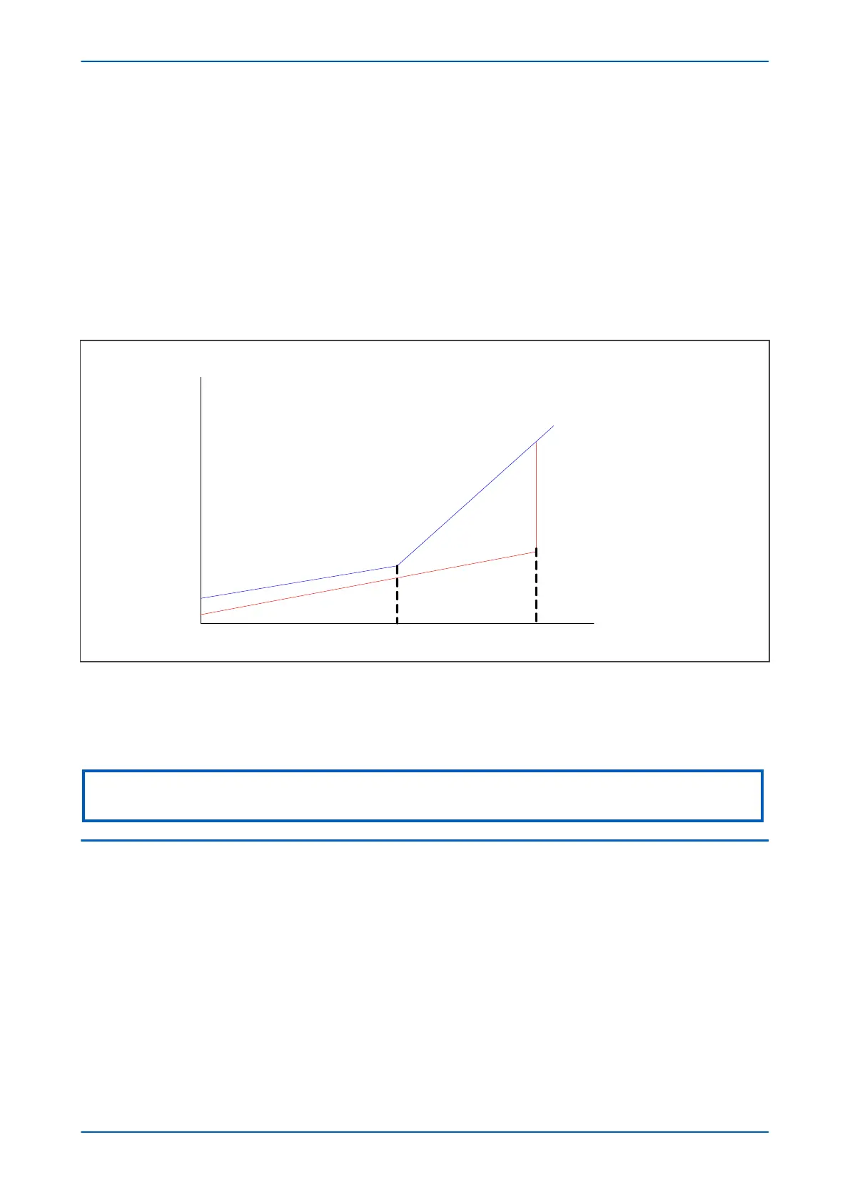
The function superimposes a second dual slope characteristic (defined by the settings IDiff Isup1 and IDiff Isup2)
onto the standard operating characteristic as shown in the figure below:
V02604
Ibias
Idiff
IS1
IS2
Restrain
Operate
Supervise
(Block or Alarm)
K1 Slope
K2 slope
Isup1
Isup2
Figure 261: Communication Asymmetry Supervision
If you choose to use the function, we recommend that you set the pickup value of the differential supervision
function (IDiff Isup1) be set at 80% of the Is1 setting and the IDiff Isup2 setting to 200% of Is2. The delay between
the condition being recognised and the alarm being raised is determined by the Idiff Sup TDelay setting.
Note:
Idiff Sup TDelay must always be set greater than the value set in Char Mod time.
2.4
GPS SYNCHRONISATION SUPERVISION
You can enable or disable GPS syncrhonisation supervision using the GPS Sync setting in the PROT COMMS/ IM64
column. It is disabled by default. There are three options with which you can enable the GPS synchronisation. Each
provides a different approach to supervising the Current Differential protection should the GPS synchronisation
signal become corrupt or unavailable. The three options available are:
●
GPS -> Standard
●
GPS -> Inhibit
●
GPS -> Restrain
If the GPS signal is available, terminals will be synchronised, and the communications paths propagation delay
times (tp1 and tp2) will be continuously calculated and retained by each terminal. Should there be a failure of the
GPS input, the synchronisation might be lost and the product will adapt its operation according to the chosen GPS
Sync setting as explained below.
P543i/P545i Chapter 18 - Supervision
P54x1i-TM-EN-1 467

 Loading...


