D
IRECTION FR091521, REVISION 1 VIVID S60N/VIVID S70N BASIC SERVICE MANUAL
3-18 Section 3-3 - Receiving and Unpacking the Equipment
PRELIMINARY
3-4-3-4 Peripheral/Accessory Connector Panel
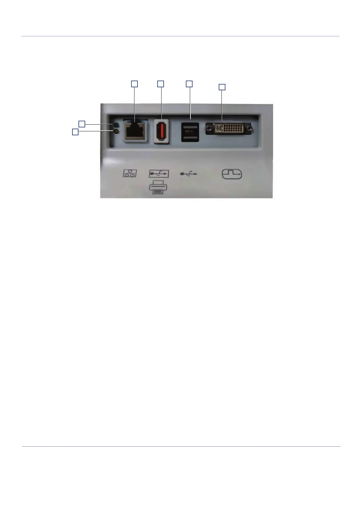
Figure 3-18 shows a view of the Vivid S60N/Vivid S70N ultrasound unit rear panel showing external
peripheral/accessory connectors.
1 Ethernet LAN connector — 1000 Base-TX Ethernet IEEE 802.3
2 Isolated USB connector (USB 1.0 only)
3 Dual USB connector
4 DVI-D Display OUT connector (DVI-I type with digital output only [DVDI-D])
5 LED - Network activity
6 LED - Network activity
3-4-4 EMI Protection
The Vivid™ S60/Vivid™ S70 has been designed to minimize the effects of Electro-Magnetic
Interference (EMI). Many of the covers, shields, and screws are provided primarily to protect the Vivid™
S60/Vivid™ S70 from image artifacts caused by this interference. For this reason, it is imperative that
all covers and hardware are installed and secured before the Vivid™ S60/Vivid™ S70 is put into
operation.
See EMI Limitations on page 2 - 4 for more information about EMI protection.
Figure 3-18 View of the Vivid S60N/Vivid S70N Peripheral/Accessory Connector Panel

 Loading...


