D
IRECTION FR091521, REVISION 1 VIVID S60N/VIVID S70N BASIC SERVICE MANUAL
Chapter 8 - Replacement Procedures 8-41
PRELIMINARY
8-3-4-5 Touch Screen Installation Procedure
1) Working from the front of the system, make sure the console is in the maximum up position and that
is aligned in the central position (not pulled to one side or the other).
2.) Fit the Touch Screen Rotaries Board (previously removed) onto the replacement Touch Screen:
3.) Using two hands, position the base of the Touch Screen on the Touch Screen chassis, placing the
base in the grooved channel and aligning the 2 screw securing holes on each side - Figure 8-40.
4.) Reconnect the Ground cable - Figure 8-41.
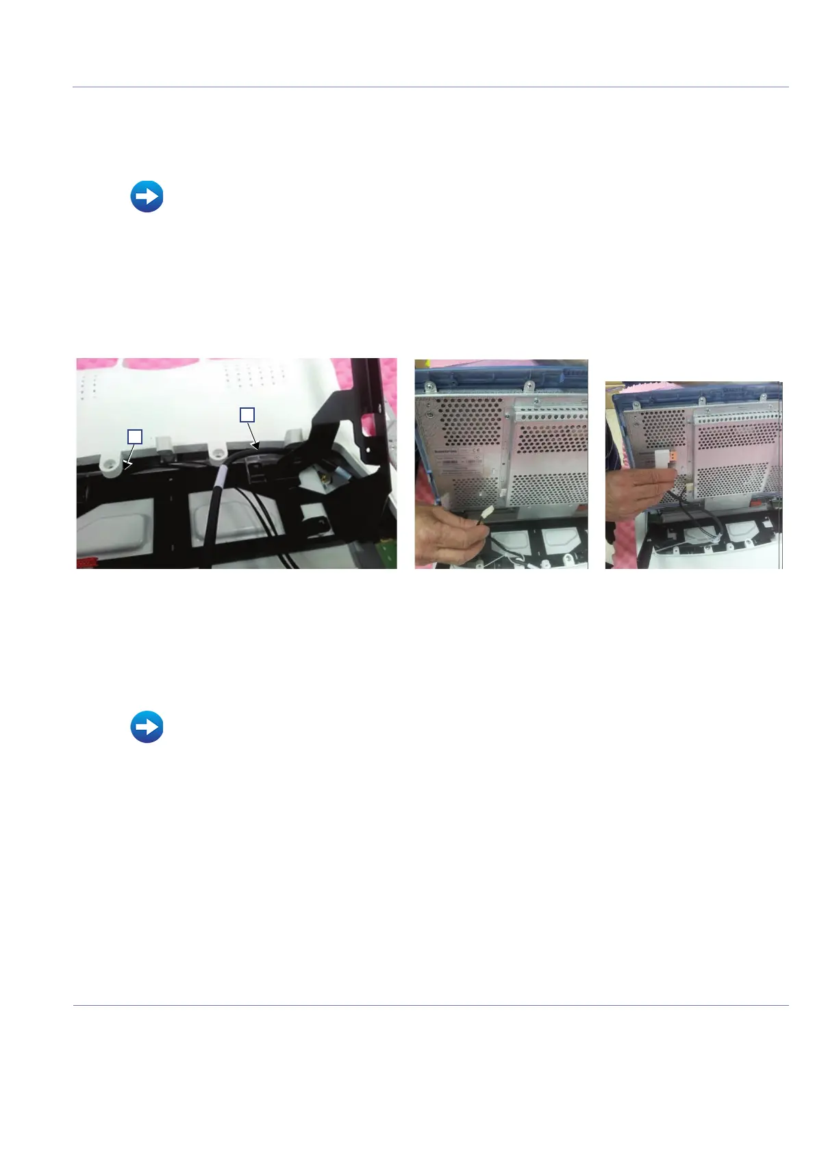
5.) Reconnect the two Touch Screen cables and make sure to route them as shown in Figure 8-46:
• Power cable behind the Touch Screen chassis screw [A]
• DP cable in front of the Touch Screen chassis screw [B]
6.) Fasten each cable with cable-securing clips.
7.) Reconnect the two flex cables to the connectors on the rear of the Touch Screen - Figure 8-43. For
easier access to the cable connectors, tilt the Touch Screen forward while connecting the cables.
8.) Fasten the 4 screws to secure the Touch Screen to the chassis - Figure 8-40.
9) Refit the following Touch Screen covers: rear, service:
• Touch Screen Rotaries Board Installation Procedure on page 8 - 43
Figure 8-46 Routing and Connecting the Touch Screen Cables
• Touch Screen Rear Cover Installation Procedure on page 8 - 37
• Touch Screen Service Cover Installation Procedure on page 8 - 35

 Loading...


