D
IRECTION FR091521, REVISION 1 VIVID S60N/VIVID S70N BASIC SERVICE MANUAL
8-100 Section 8-5 - Electronic Cage Components - Replacement Procedures
PRELIMINARY
8-5-6 Module Memory DDR Replacement Procedure
Note: Both Module Memory DDR circuit boards must be renewed when replacing them.
8-5-6-1 Tools
Appropriate Phillips and flat screwdrivers.
8-5-6-2 Time Required
15 minutes
8-5-6-3 Preparations
Shut down the Vivid™ S60/Vivid™ S70 ultrasound unit, as described in Power Shut Down on page 4 - 7.
8-5-6-4 Module Memory DDR Removal Procedure
The Module Memory DDR is located on the BEP (the obverse side that is not visible when opening the
cage door to view the BEP). The front view of the BEP is shown in Figure 8-121 on page 8-96. The BEP
has to be removed to access the Module Memory DDR, which is shown in Figure 8-124 below.
1.) Remove the BEP:
2.) Place the BEP on a clean flat work surface with the Module Memory DDR uppermost.
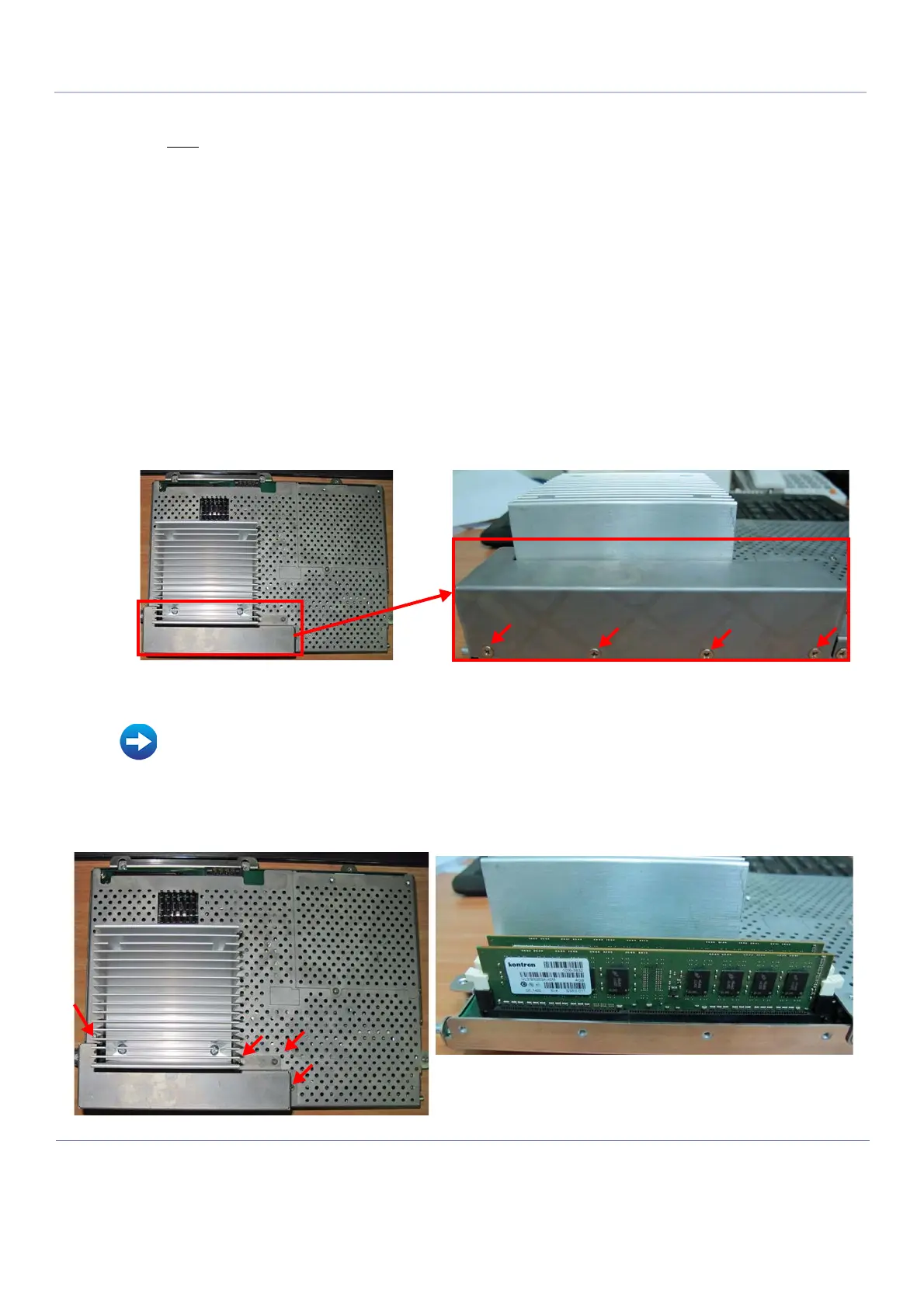
3.) Remove the Module Memory DDR cover by unscrewing 8 screws as indicated in Figure 8-124,
above and Figure 8-125.
Refer to Table 9-14 on page 9-13.
Figure 8-124 Module Memory DDR Replacement
• BEP Removal Procedure on page 8 - 94
Figure 8-125 Removing the Module Memory DDR Cover
Two HD Module circuit boards shown above after the
cover has been removed

 Loading...


