D
IRECTION FR091521, REVISION 1 VIVID S60N/VIVID S70N BASIC SERVICE MANUAL
8-44 Section 8-3 - Control Console Components - Replacement Procedures
PRELIMINARY
8-3-6 Operator Panel Keyboard Assembly Replacement Procedure
8-3-6-1 Tools
Phillips screwdriver, flat screwdriver, and a 4 mm Allen key.
8-3-6-2 Time Required
25 min
8-3-6-3 Preparation
Shut down the Vivid™ S60/Vivid™ S70 ultrasound unit, as described in Power Shut Down on page 4 - 7.
8-3-6-4 Operator Panel Keyboard Assembly Removal Procedure
Note: If the OPIO Basket is attached, remove it from the keyboard interface column (refer to OPIO
Basket Removal Procedure on page 8 - 26).
1) Working from the front of the system, raise the console to the maximum up position.
2) Make sure that the console is aligned in the central position (not pulled to one side or the other).
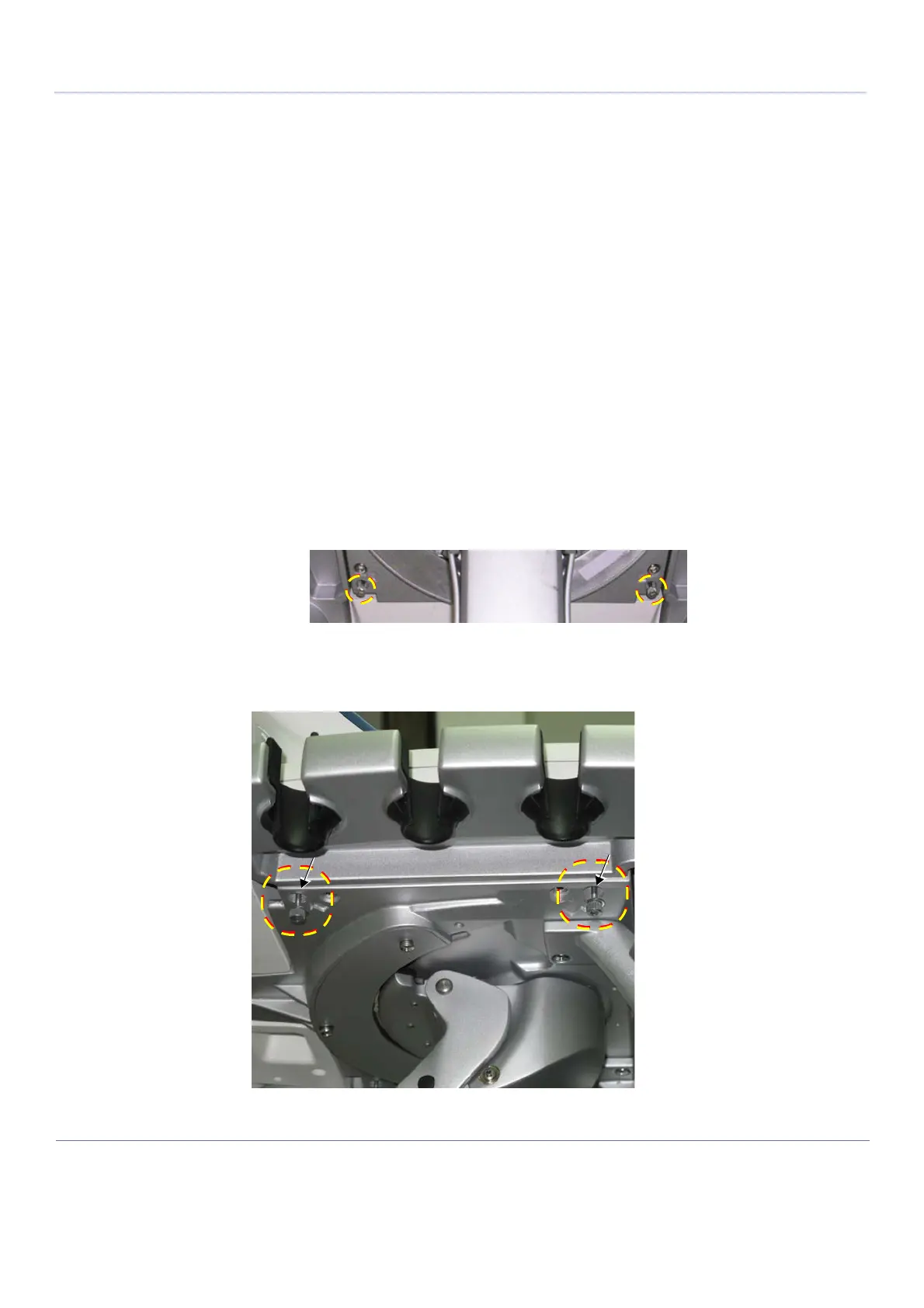
Note: Adjacent to each of the four Allen screws (two on the left; two on the right) there is an arrow
marking the position of the screws for easy identification:
3) Working from beneath the keyboard assembly, loosen the two Allen screws on the system’s right
side (arrows marked in the figure indicate the screw locations) as shown in Figure 8-49 below.
Refer to Table 9-11 on page 9-10.
Figure 8-49 Removing the Allen Screws under Keyboard Assembly - Right Side

 Loading...


