D
IRECTION FR091521, REVISION 1 VIVID S60N/VIVID S70N BASIC SERVICE MANUAL
Chapter 8 - Replacement Procedures 8-45
PRELIMINARY
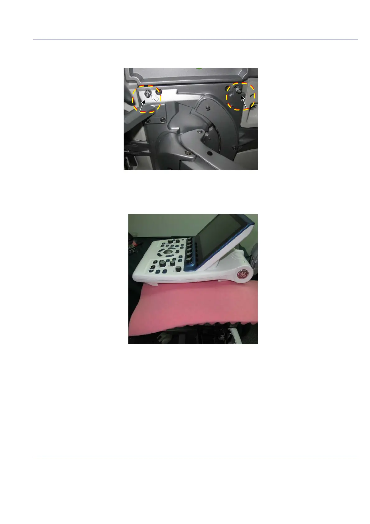
4) Loosen the two captive Allen screws on the left side, as shown in Figure 8-50 below (arrows marked
in the figure indicate the screw locations).
5) Before proceeding, place some protective sponge beneath the Keyboard Assembly unit to protect
it from being damaged during the removal procedure - see Figure 8-51 below.
Figure 8-50 Loosening the Captive Allen Screws beneath Keyboard Assembly - Left Side
Figure 8-51 Protective Sponge shown Beneath OPIO

 Loading...


