July 2010 11 – 125
11.3.2 The LOGIC diagram
With the LOGIC DIAGRAM function, the time course of the dynamic change of PLC
operands (M, I, O, T, C) can be displayed.
Call
8 Soft key to call the LOGIC DIAGRAM function.
Selecting the
operands
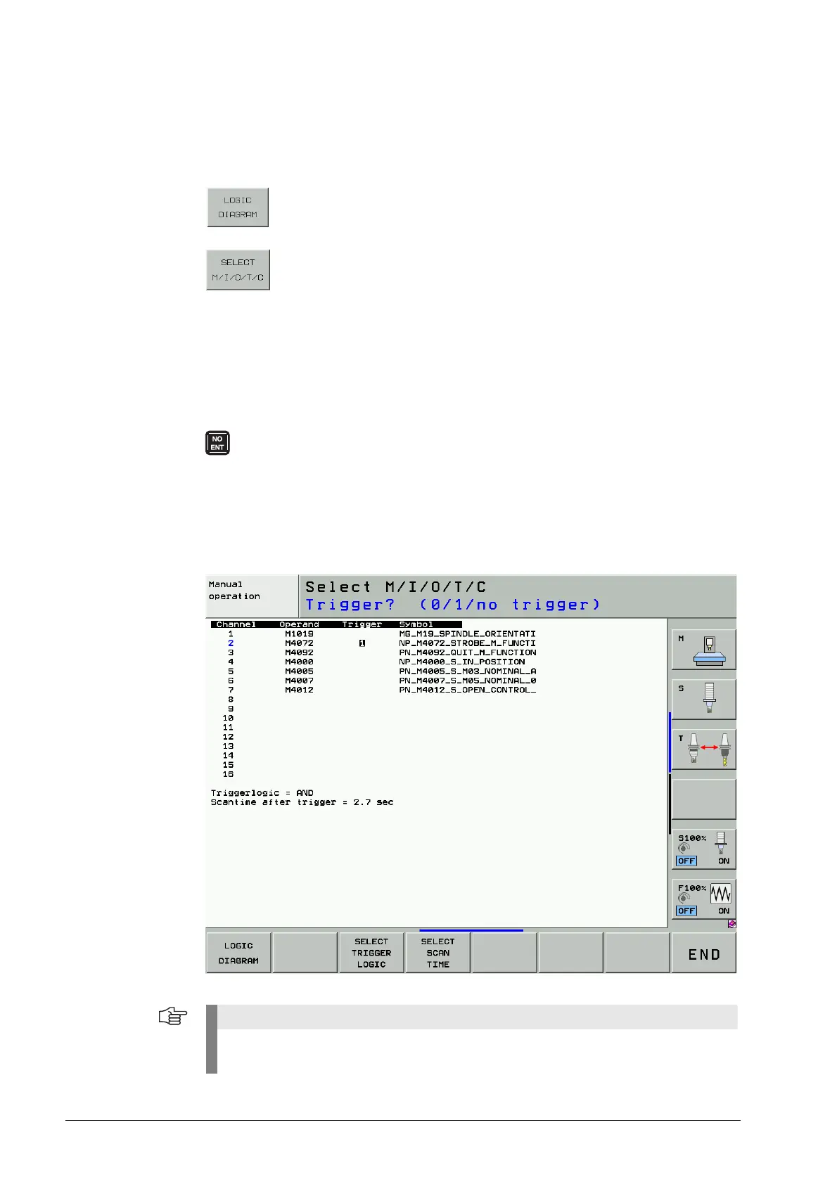
8 Display selection table.
In the displayed table the desired operands can be selected. The individual positions in the table
are interrogated using dialog. Incorrect entries can be deleted with the DEL key. A trigger
condition can be set for each operand. 512 states are recorded each before and after a trigger
event. The following trigger conditions are possible:
Figure: Example for the operand selection
1 Record when operand is logical on (Triggering on positive edge)
0 Record when operand is logical zero (Triggering on negative edge)
No trigger:
If no trigger condition is entered for any of the operands, the operand states are
traced the operands are recorded continuously. The 1024 most recent states
remain saved.
e.g.: 0 I5 1 Trigger on positive edge
1 O6 0 Trigger on negative edge
2 M2003 No trigger
The WATCH LIST can also be called before and with the ADD TO LOGIC DIAGRAM soft key
operands can be added to the logic diagram.

 Loading...


