27 – 522 HEIDENHAIN Service Manual iTNC 530
Adapter connector
11 µA
PP
/ 1 V
PP
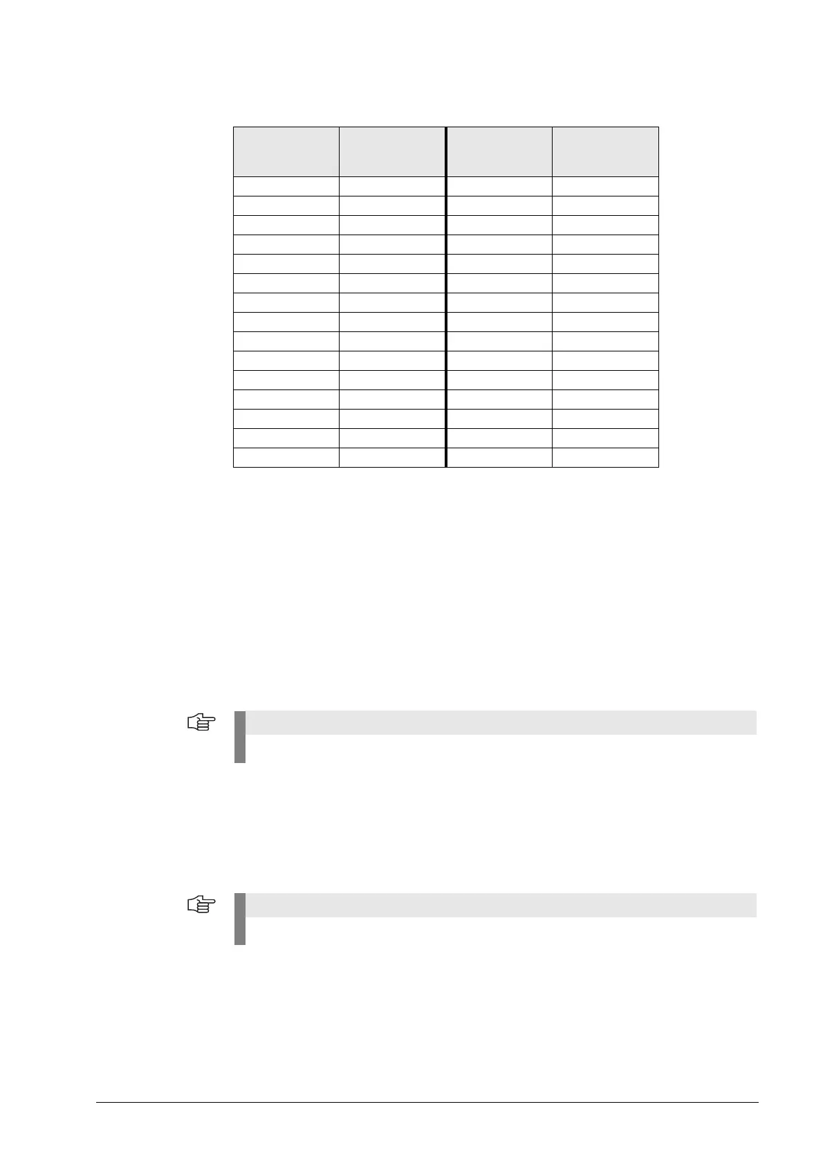
Pin layout of D-sub connector (female) and D-sub connector (male):
27.11.2 Speed encoders
See “X15 to X20, X80 to X87: Speed encoder 1 VPP” on page 27 – 463.
27.12 Inverters and Motors
Inverter systems are powered via PWM outputs of the control. --> See “X51 to X64:
PWM-output” on page 27 – 480.
The motor encoders are connected to the speed encoder interface of the control.
--> See “X15 to X20, X80 to X87: Speed encoder 1 VPP” on page 27 – 463.
27.13 Interface Boards for the SIMODRIVE System 611D
The HEIDENHAIN expansion boards for the SIMODRIVE system receive PWM signals from the
control and converts them. --> See “X51 to X64: PWM-output” on page 27 – 480.
D-sub connector
(female)
15-pin
Pin layout D-sub
connection
(male) 15-pin
Pin layout
1+5 V (U
P
)1 +5 V (U
P
)
2 0 V (U
N
)2 0 V (U
N
)
3A+30°+
4A–40°–
50 V50 V
6 B+ 6 90°+
7 B– 7 90°–
80 V80 V
9 +5 V 9 +5 V
10 R+ 10 R+
11 0 V 11 0 V
12 R– 12 R–
13 0 V 13 0 V
14 Not assigned 14 Not assigned
15 Not assigned 15 Not assigned
For further information, refer to the Service Manual "Inverter Systems and Motors".
For further information, refer to the Service Manual "Inverter Systems and Motors".

 Loading...


