EasyManuals Logo

HEIDENHAIN ITNC 530 Service Manual

HEIDENHAIN ITNC 530
696 pages
To Next Page IconTo Next Page
To Previous Page IconTo Previous Page
Page #654 background imageLoading...
Page #654 background image
1– 654 HEIDENHAIN Service Manual iTNC 530
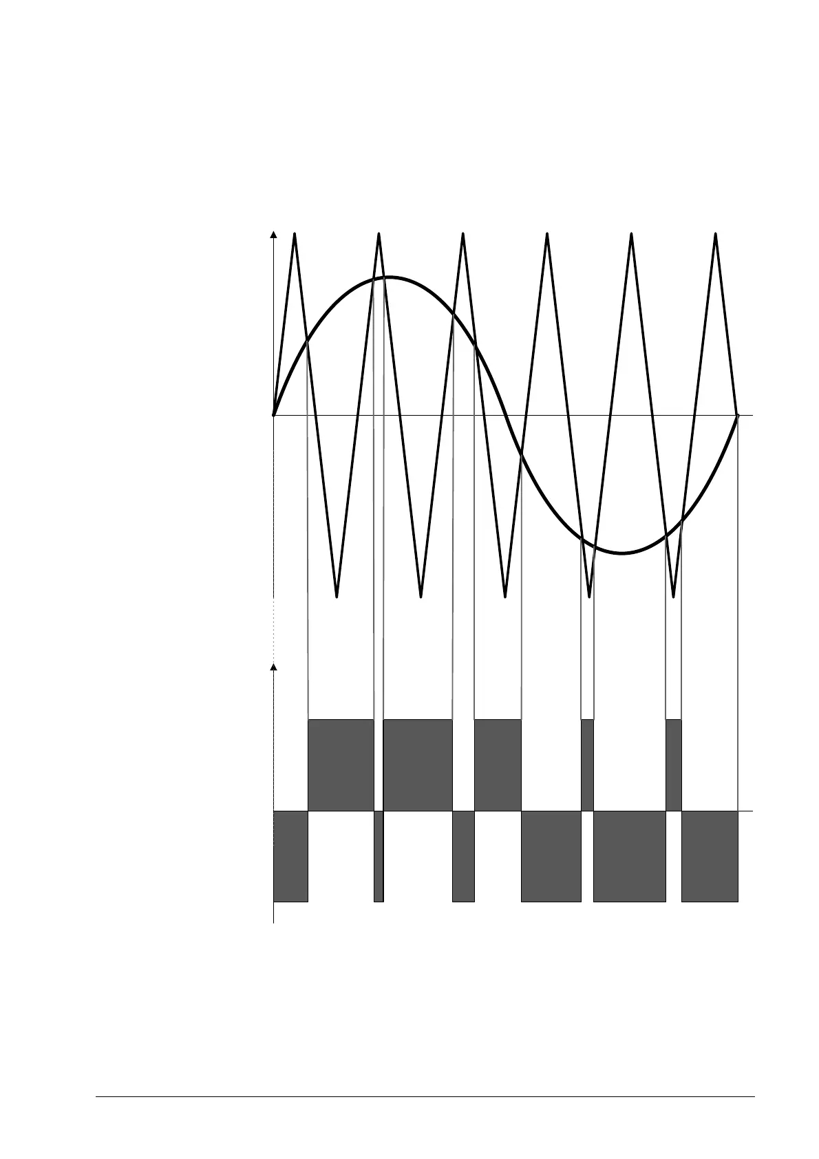
1.3 PWM Signals
Digital axes and spindles are driven with PWM signals.
PWM is the abbreviation "Pulse Width Modulation". The information (speed, torque) for the
output stages is converted into a pulse and pause ratio.
The PWM signal is generated in the HEIDENHAIN control and is transferred to the inverter via
PWM interfaces.
The output signal of the current controller is compared to a delta voltage (e.g., 5 kHz fixed
frequency) to create the PWM signal. At each interface of the current controller signal and the
delta voltage there is a switchover from pulse to pause.
PWM

Table of Contents

Other manuals for HEIDENHAIN ITNC 530

Questions and Answers:

Question and Answer IconNeed help?

Do you have a question about the HEIDENHAIN ITNC 530 and is the answer not in the manual?

HEIDENHAIN ITNC 530 Specifications

General IconGeneral
Control TypeCNC
Look-aheadYes
Spindle controlYes
Touch probe cyclesYes
Operating voltage24 V DC
ProgrammingConversational and DIN/ISO programming
InterpolationLinear, Circular, Helical
Data InterfaceEthernet, USB, RS-232
Memory1 GB
Programming LanguageHEIDENHAIN plain language
Operating ModesManual, Automatic, MDA
Software OptionsVarious software options available

Related product manuals