EasyManuals Logo

HEIDENHAIN ITNC 530 Service Manual

HEIDENHAIN ITNC 530
696 pages
To Next Page IconTo Next Page
To Previous Page IconTo Previous Page
Page #645 background image
July 2010 1 – 645
1 Annex: Principle of Function of the iTNC 530 Control
1.1 Introduction
This chapter gives you block diagrams and brief explanations of the principle of function of the
iTNC 520 control.
Fundamental knowledge about controls, encoders, drives, electronics and mechanics simplifies
error diagnosis and is often indispensible for successful servicing.
Ask your machine manufacturer for detailed or special explanations (e.g., machine functions,
circuit diagram of the machine)!
1.2 The Control Loop
The control loop for
analog axes/
spindles
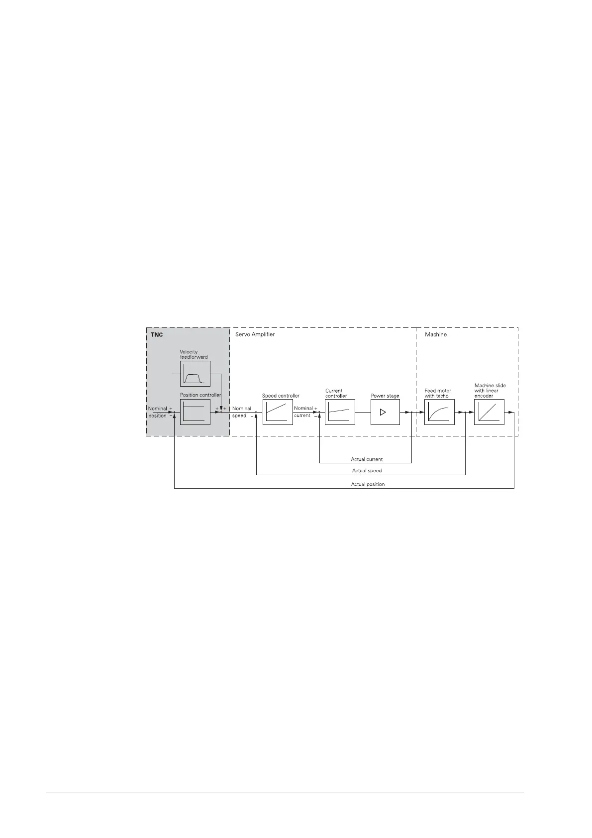
The iTNC 530 can also control analog axes / spindles.
The position controller is located in the control, speed and current controller in the analog servo
amplifier.
The analog servo amplifiers are supplied with voltage values of - 10 V and + 10 V (speed
command interface).
Figure: Simplified illustration for the analog control loop

Table of Contents

Other manuals for HEIDENHAIN ITNC 530

Questions and Answers:

Question and Answer IconNeed help?

Do you have a question about the HEIDENHAIN ITNC 530 and is the answer not in the manual?

HEIDENHAIN ITNC 530 Specifications

General IconGeneral
Control TypeCNC
Look-aheadYes
Spindle controlYes
Touch probe cyclesYes
Operating voltage24 V DC
ProgrammingConversational and DIN/ISO programming
InterpolationLinear, Circular, Helical
Data InterfaceEthernet, USB, RS-232
Memory1 GB
Programming LanguageHEIDENHAIN plain language
Operating ModesManual, Automatic, MDA
Software OptionsVarious software options available

Related product manuals