20 – 344 HEIDENHAIN Service Manual iTNC 530
20.2 Analog Speed Command Interface
20.2.1 Introduction
For the operation of analog axes and spindles, the position controller is located in the MC, the
speed and current controller in the servo amplifier.
The "result" of the position control is transferred to the analog servo amplifier via the ± 10 V
speed command interface.
For analog drives DC motors are often used.
Analog speed value
outputs
Following analog speed command outputs are located on the MC 42x (B/C):
X8
X9
On each of these D-Sub connectors there are several analog channels.
Assignment of the
speed value
outputs
MP 100 is read from the right to the left and contains the information which axis is the first, the
second, the third axis, etc.
20.2.2 Possible causes of error
Mechanical defects
Wear and tear of mechanical parts
Aging of the machine
Motor (carbon brushes, tachometer brushes, winding, etc.) defective
Servo amplifier defective
Defective cables
Poor shielding and grounding
Errors in the NC or PLC software
Defective nominal speed value interface of the MC (X8, X9)
MP 100 must not be changed!
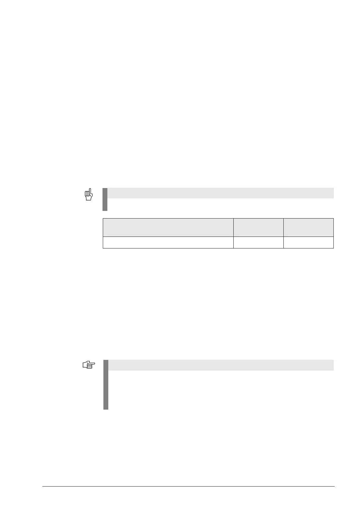
Assignment of the speed command outputs
in the machine parameters
Axes Spindles
Machine parameters MP 120.x MP 121.x
There is a large variety of possible error causes.
Profound knowledge of the machine and the interaction of the components is very helpful
especially for this type of errors.
When error messages are generated, press the HELP key. You will obtain information on
possible error causes and tips for error elimination.

 Loading...


