July 2010 23 – 391
23.3 Checking the Power Supply
Power is supplied on the following connectors and pins:
Check whether the power supply is in order:
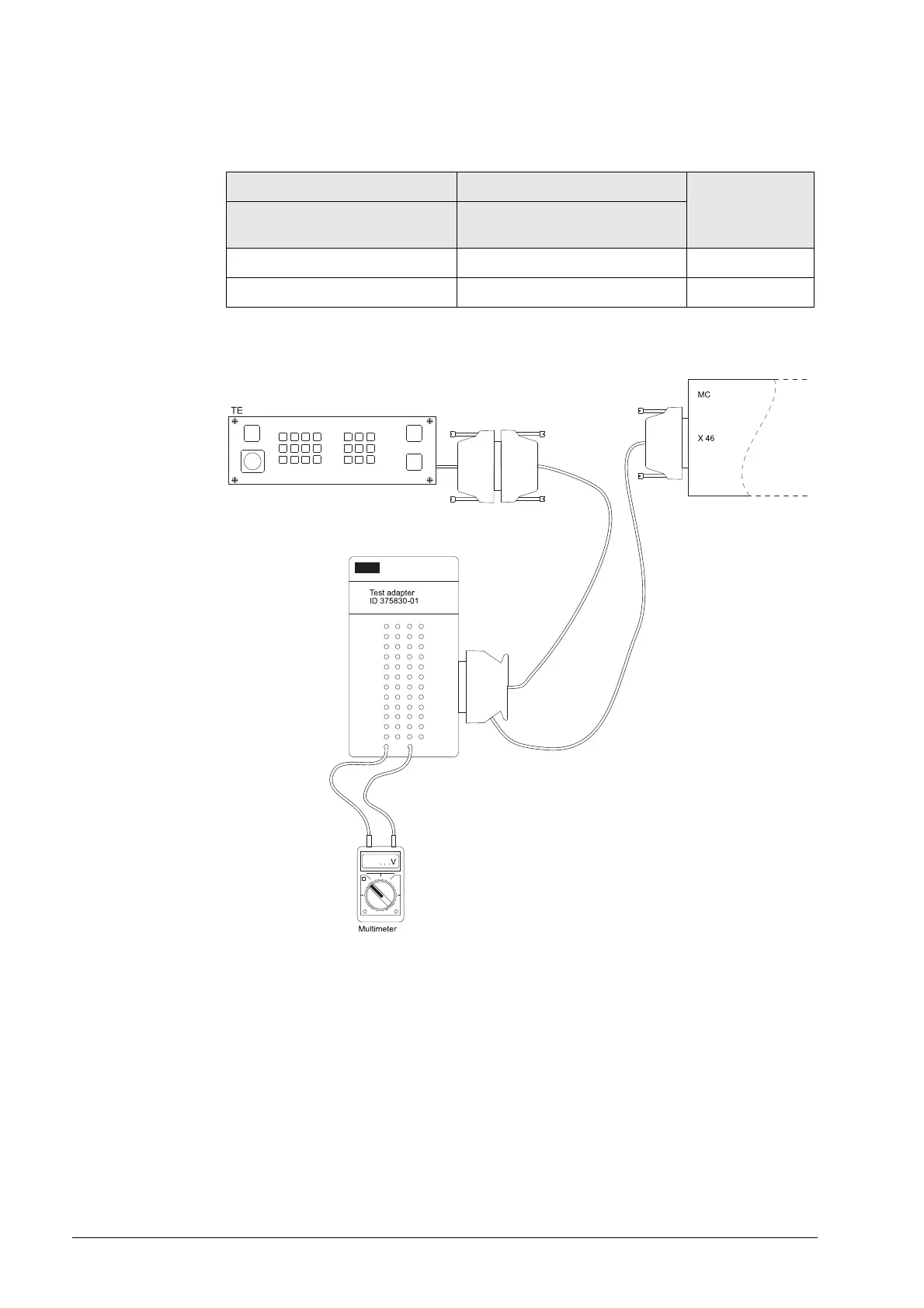
Measuring setup
with test adapter
Figure: Voltage management with test adapter
Procedure:
8 Shut down the control and switch off the machine.
8 Connect the test adapter between MB and control (See “Test Adapter” on page 29 – 562).
8 Switch the machine back on again.
8 Check the supply voltage at the pins concerned with a multimeter.
MB 420 MB 520 Pin layout
Connector X1
(or connector X46 on the MC)
Connector X3
(or connector X46 on the MC)
Pin 34, 35 Pin 34, 35 0 V
Pin 36, 37 Pin 36, 37 24 V (PLC)

 Loading...


