27 – 500 HEIDENHAIN Service Manual iTNC 530
X4:
PLC outputs
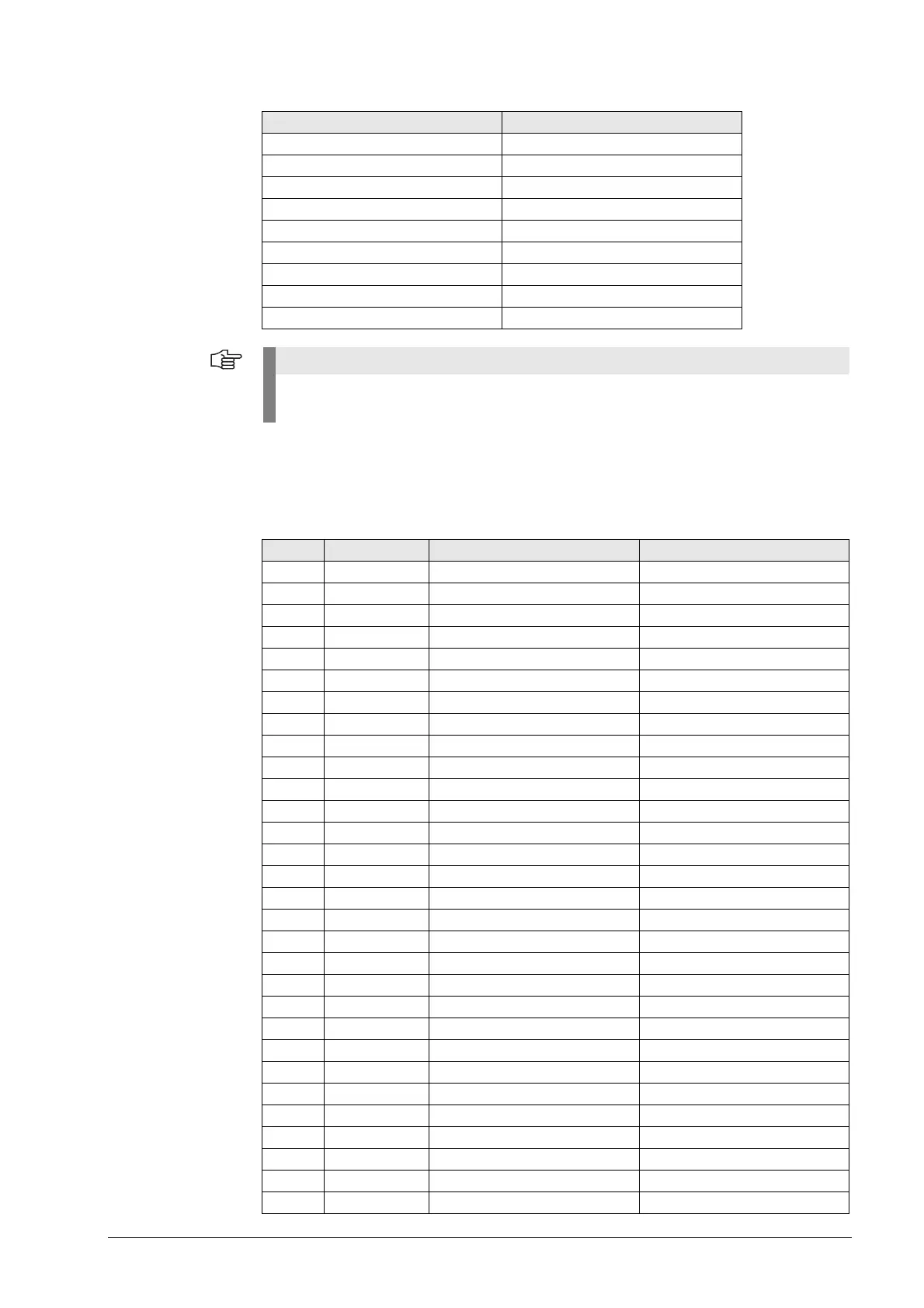
27.7.3 Pin layouts on MB 520
X3:
Connection to MC
D-sub connector, 37-pin
Connecting cable ID 263 954-xx:
Terminal Pin layout
1O0
2O1
3O2
4O3
5O4
6O5
7O6
8O7
90 V
These PLC outputs are connected to the control via the D-Sub connector X1 (MC, connector
X46).
X3 PLC input Meaning of the keys SN/Signal
1 I128 X minus S14
2 I129 Y minus S27
3 I130 Z minus S28
4 I131 IV minus S29
5 I132 V minus S30
6 I133 X plus S16
7 I134 Y plus S3
8 I135 Z plus S2
9 I136 IV plus S1
10 I137 V plus S4
11 I138 Select tool change S7
12 I139 Unclamp tool S8
13 I140 Chip conveyor back S25
14 I141 Unlock working space S38
15 I142 Chip conveyor S12
16 I143 Spindle start S34
17 I144 Spindle stop S33
18 I145 Coolant, external (M08) S11
19 I146 NC start STRT from terminal strip X15
20 I147 NC stop STP from terminal strip X14
21 I148 Rapid traverse S15
22 I149 Retract axis S17
23 I150 Coolant, internal (M07) S24
24 I151 Control voltage ON STSP from terminal strip X13
25 I152 Additional coolant S37
26 O0 NC start lamp From terminal strip X15
27 O1 NC stop lamp From terminal strip X14
28 O2 Control voltage lamp On From terminal strip X13
29 O3 Vacant
30 O4 Vacant

 Loading...


