July 2010 27 – 501
X10:
To a transfer unit
D-sub connector, 15-pin
Connecting cable ID 629 663-xx:
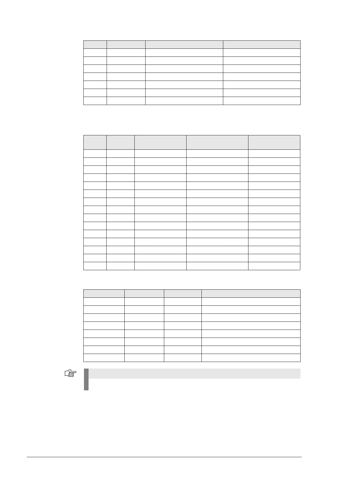
X11:
Vacant PLC inputs
31 O5 Vacant
32 O6 Vacant
33 O7 Vacant
34 0 V
35 0 V
36 +24 V
37 +24 V
X3 PLC input Meaning of the keys SN/Signal
X10 PLC
Input
Meaning
of the keys
SN/Signal Color
1 Vacant VI plus S5 White
2 Vacant VI minus S31 Brown
3 Vacant Jog spindle to left S20 Green
4 Vacant Jog spindle to right S21 Yellow
5 Vacant Permissive mode S18 Violet
6 Vacant FN1 S10 Brown/Green
7 Vacant FN2 S23 Gray
8 Vacant FN3 S36 Pink
9 Vacant Not assigned Vacant input X11/1 Blue
10 Vacant Not assigned Vacant input X11/2 Red
11 Vacant Not assigned Vacant input X11/3 Black
12 Vacant Not assigned Vacant input X11/4 White/Green
13 Vacant Not assigned Vacant input X11/5 Red/Black
14 Vacant Not assigned Vacant input X11/6 Yellow/Black
15 Vacant Not assigned Vacant input X11/7 Blue/Black
Terminal X11 PLC operand Meaning Signal
1 Ixxx Vacant Vacant input to X10/9
2 Ixxx Vacant Vacant input to X10/10
3 Ixxx Vacant Vacant input to X10/11
4 Ixxx Vacant Vacant input to X10/12
5 Ixxx Vacant Vacant input to X10/13
6 Ixxx Vacant Vacant input to X10/14
7 Ixxx Vacant Vacant input to X10/15
8+24V
These PLC inputs are connected to the control via the D-Sub connector X10.

 Loading...


