27 – 516 HEIDENHAIN Service Manual iTNC 530
27.10.3 Pin layouts for PL 510
X1:
PLC expansion on
the MC 422 (B)
See “X47: PLC expansion for PL 510 to the MC 422 (B/C)” on page 27 – 476.
X1:
PLC expansion on
the MC 420
See “X147: PLC Expansion for PL 510 on the MC 420” on page 27 – 484.
X2:
PLC expansion
PL 510 on the
PL 510
D-sub connector, 26-pin
Pin layout on PLB 510 basic module:
X3:
Supply voltage
for logic
Pin layout on PLB 510 basic module:
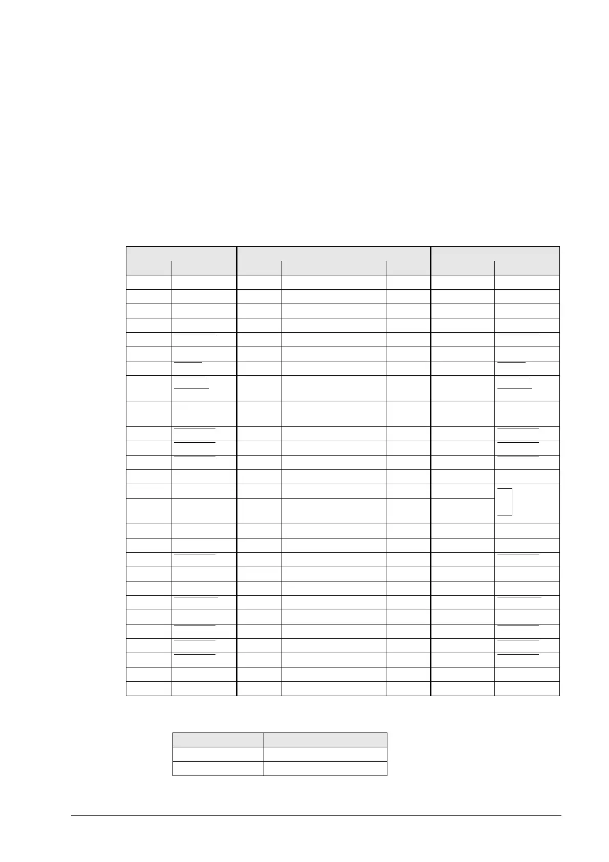
PL 510 Connecting cable ID 371 046-xx PL 510 on PL 510
Male Pin layout Female Male X1 Socket Pin layout
10 V 1Black 11 0 V
2 0 V 2 Violet 2 2 0 V
30 V 3 33 0 V
4 Do not assign 4 4 4 Do not assign
5 Address 6
5 Yellow 5 5 Address 6
6 INTERRUPT 6 Blue 6 6 INTERRUPT
7 RESET 7Red 77 RESET
8WRITE
EXTERN
8Gray 88 WRITE
EXTERN
9WRITE
EXTERN
9Pink 99 WRITE
EXTERN
10 Address 5 10 Green 10 10 Address 5
11 Address 3 11 White 11 11 Address 3
12 Address 1 12 Brown 12 12 Address 1
13 Do not assign 13 13 13 Do not assign
14 +5 V (output) 14 White/Blue 14 14
15 +5 V
(feedback)
15 Brown/Blue 15 15
16 PCB ident. 2 16 White/Pink 16 16 PCB ident. 2
17 PCB ident. 1 17 Pink/Brown 17 17 PCB ident. 1
18 Address 7
18 Brown/Green 18 18 Address 7
19 Serial IN 1 19 WH/GY 19 19 Serial IN
20 EM. STOP 20 Gray/Brown 20 20 EM. STOP
21 Serial OUT
21 White/Yellow 21 21 Serial OUT
22 Serial OUT 22 Yellow/Brown 22 22 Serial OUT
23 Address 4
23 White/Green 23 23 Address 4
24 Address 2 24 GY/PK 24 24 Address 2
25 Address 0 25 Red/Blue 25 25 Address 0
26 26 26 26
Housing External shld. Housing External shield Housing Housing External shld.
Connect. terminal Pin layout
1 +24 Vdc (20.4 V to 28.8 V)
2+0 V

 Loading...


