July 2010 25 – 425
25.5 Error Diagnosis on Laser Touch Probe
Control impaired? If you suspect that a damaged laser system or a laser system into which liquid has penetrated
impairs the function of the control:
8 Disconnect the touch probe and observe the reaction. -->
See “Deselecting and Disconnecting the Touch Probe” on page 25 – 426.
Visual inspection
Check whether the laser system or the cable is damaged, etc.
Checking the LEDs
Checking the
"Ready" bridge
In the Laser Touch Probe the Ready signal is bridged.
This means that the Ready signal must always be present if a laser touch probe is connected.
Proceed as follows to check the Ready bridge:
8 Shut down the control and switch off the machine.
8 Disconnect the keypad cable on connector X13 from the MC.
8 Use a multimeter which you set to "beep" mode or to ohm measurement.
8 Apply the needle tips to the pins 1 and 4 of the touch probe cable. --> A beep must be heard
or a low ohmic value displayed.
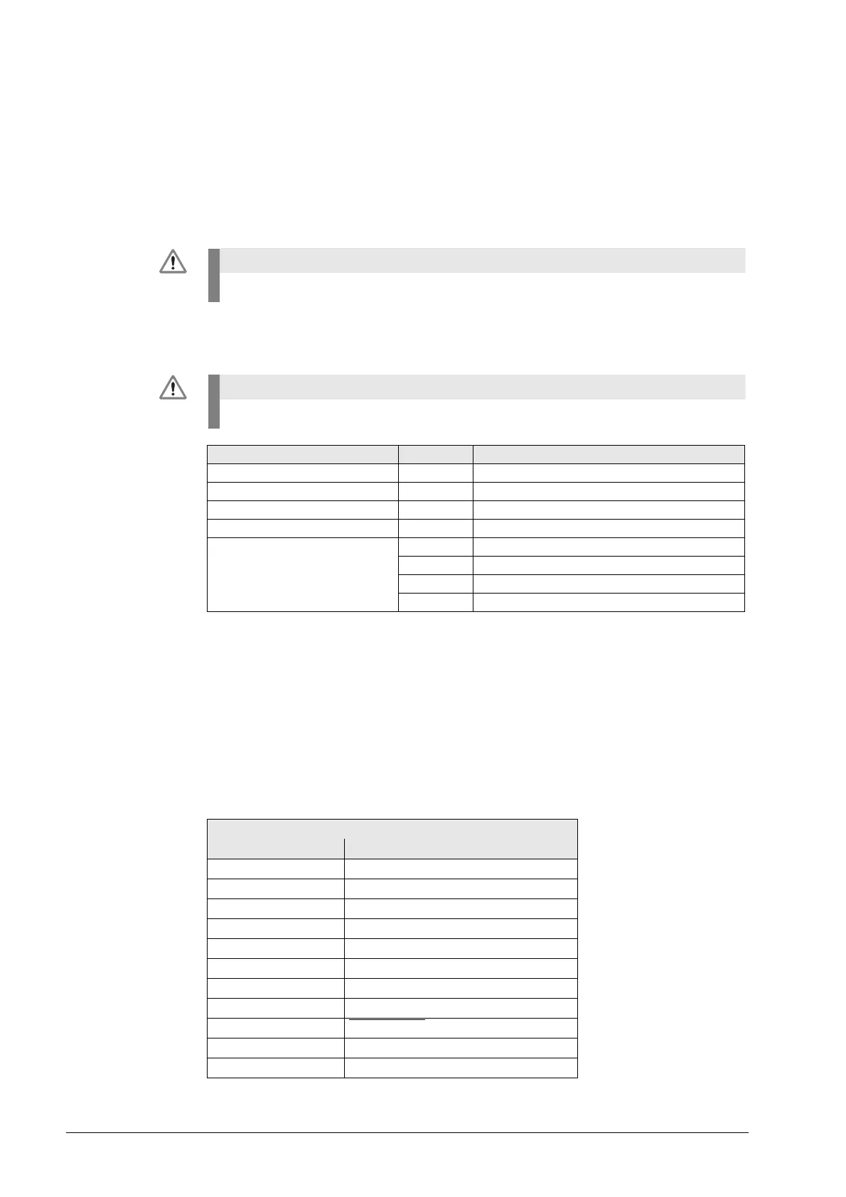
Assignment at the interface X13 (D-SUB, 9-pin, 2-row):
Laser radiation! Do not stare into the beam! Laser class 2.
Laser radiation! Do not stare into the beam! Laser class 2.
Optical Status Indicator LED Function
Laser ON Green Input for enabling transmission
Alignment Green Laser adjustment OK (signal > 95 %)
Laser OK Green Laser output OK (signal > 75 %)
Output Red DYN output (signal > 50 %)
Mode White Operating mode 0
Green Operating mode 1
Red Operating mode 2
Yellow Operating mode 3
MC 42x(B)
Female Assignment X13 (TT)
1 Readiness
2 0 V (U
N
)
3 Do not assign
4+15 V ±5% (U
P
)
5 Do not assign
6 Do not assign
7 +5 V ±5% (U
P
)
8 Trigger signal
9 Trigger signal
––
Hsg. External shield

 Loading...


