25 – 424 HEIDENHAIN Service Manual iTNC 530
By means of logic diagram:
8 Switch on the machine.
8 Turn the feed-rate potentiometer to a low value.
8 Call the logic diagram. --> See “The LOGIC diagram” on page 11 – 125
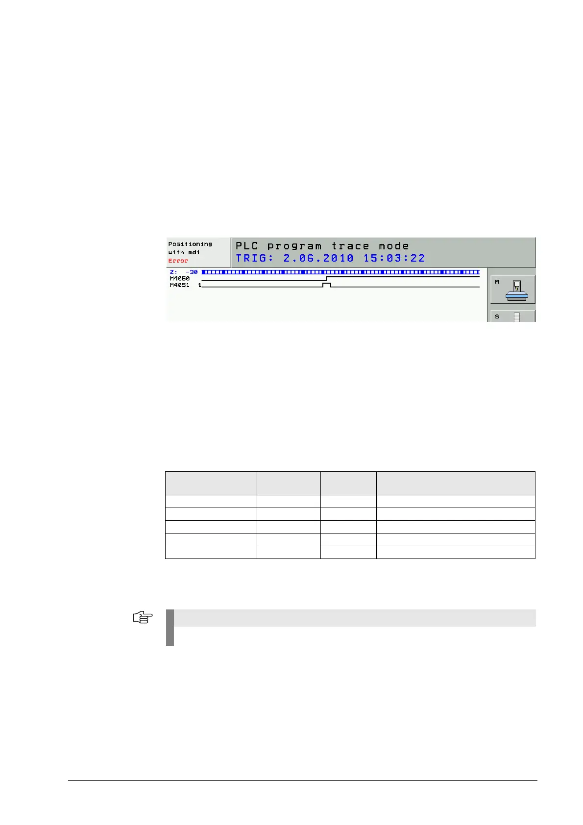
8 Enter the operands M4050 and M4051 and place the trigger on M4051.
8 Start the recording.
8 Start the probing cycle with the TT (tool touch probe).
8 Check the marker 4050.
If the probe is ready, this marker has the status zero!
8 Deflect the tool touch probe by hand.
8 Check marker 4051.
If the touch probe is deflected, this marker changes to one!
In the machine display appears the message Stylus deflected.
By means of test adapter:
8 Switch off the machine.
8 Connect the test adapter between MC (connector X13) and touch probe cable.
--> See “Test Adapter” on page 29 – 562.
8 Switch on the machine.
8 Turn the feed-rate potentiometer to zero.
8 Start the probing cycle with the TT (tool touch probe).
8 Deflect the tool touch probe by hand.
8 Measure the respective voltage:
The 0 V reference potential (U
N
) is on pin 2. --> See “X13: Connection of the touch probe for tool
measurement” on page 27 – 462
Signal Connector
X13
Voltage Meaning
Pin 4 +15 V Power supply
Pin 7 + 5 V Power supply
Ready signal Pin 1 +15 V Probe is ready
Negated trigger signal Pin 9 + 5 V Probe is ready, at rest
Negated trigger signal Pin 9 0 V Probe already deflected.
If available, you can also connect an identical TT probe to test the functionality!

 Loading...


