27 – 462 HEIDENHAIN Service Manual iTNC 530
Two EA 652 can be connected to the MC 422 via the APE 652. This is necessary for example on
large machines or on machines with swivel heads.
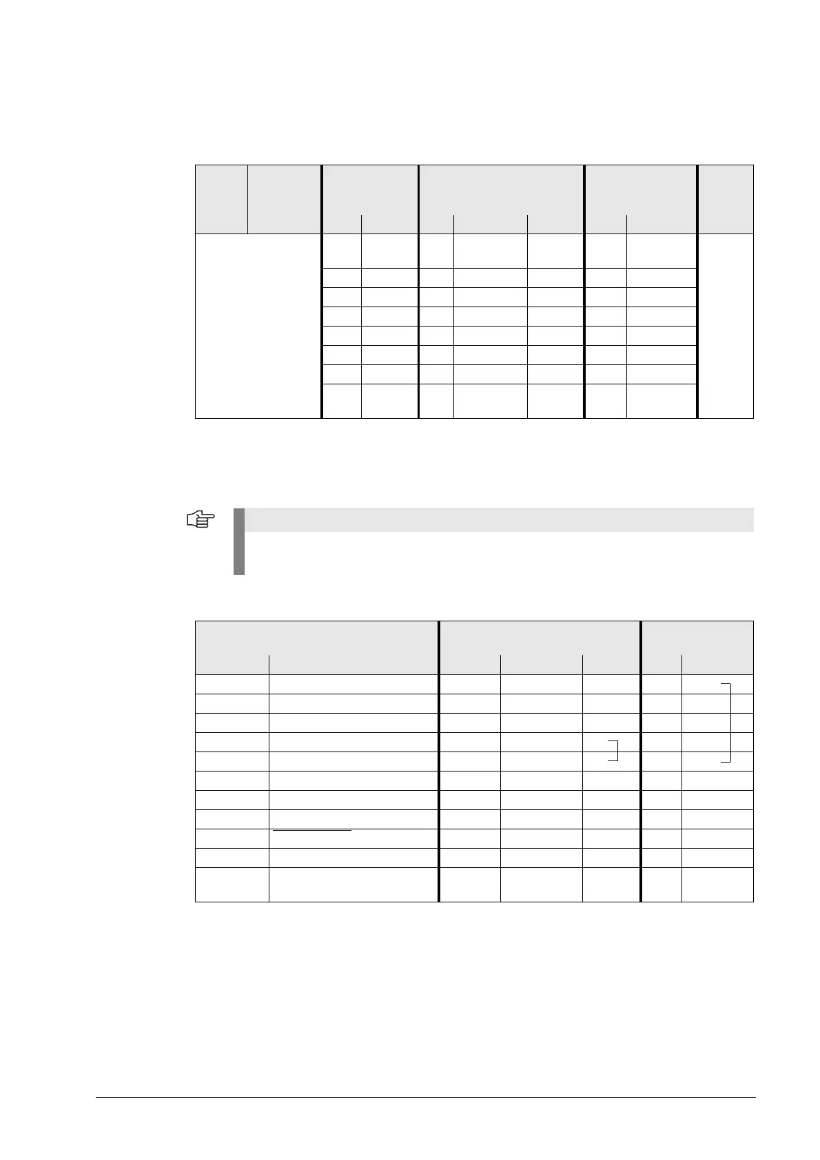
Pin layout for TS 632 with 2 EA 652 via the APE 652:
X13:
Connection of the
touch probe for tool
measurement
D-sub connector, 9-pin
Pin layout on the MC 42x (B/C):
Pin layout on adapter cable and touch probe:
MC 422 Adapter
cable
310 197-xx
APE 652
354 656-xx
Conneacting cable
ID 336 157-xx
EA 652
346 322-xx
TS 632
Male Female
Male
Color Female Male Color
Assignment see
above!
77 7White/
Brown
77White/
Brown
55 5Gray 5 5 Gray
33 3Yellow 3 3
22 2Brown 2 2 Brown
66 6Blue 6 6 Blue
1 1 1 White 1 1 White
4 4 4 Green 4 4 Green
Hsg. Hsg. Hsg.
Ext. shield
Hsg. Hsg.
The interface complies with the requirements of EN 61800-5-1 for "protective extra-low
voltage" (PELV).
MC 42x (B/C) Adapter cable ID 335 332-xx TT 130
296 537-xx
Female Pin layout Male Color Female Male Color
1 Readiness 1 Pink 6 6
2 0 V (U
N
) 2 White/Green 1 1 White
3 Do not assign 3
4 +15 V ±5% (U
P
) 4 Brown/Green 2 2 Brown
5 Do not assign 5 5 5
6 Do not assign 6
7 +5 V ±5% (U
P
)7
8 Trigger signal 8 Brown 3 3 Green
9 Trigger signal
a
9 Green 4 4 Yellow
–– –– 77
Hsg. External shield Hsg.
Ext. shield
Hsg. Hsg.
a. Stylus at rest means logic level HIGH.

 Loading...


