July 2010 27 – 457
27.2.2 Pin Layouts on the MC and CC
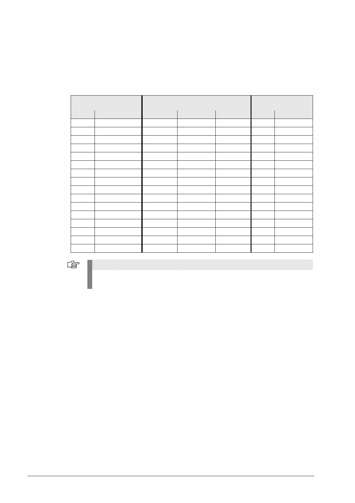
X1 to X6,
X35 to X38,
X201 to X214:
Position encoder
1V
PP
D-sub connector, 15-pin
MC 42x (B/C), CC 424 (B) Adapter cable ID 309 783-xx
Adapter cable ID 310 199-xx
Measuring system
Male Pin layout Female Color Female Male Color
1+5 V (U
P
) 1 Brown/Green 12 12 Brown/Green
2 0 V (U
N
) 2 White/Green 10 10 White/Green
3A+ 3 Brown 5 5Brown
4A– 4 Green 6 6Green
5 Do not assign 5
6 B+ 6 Gray 8 8 Gray
7 B– 7 Pink 1 1 Pink
8 Do not assign 8
9 +5 V (sensor) 9 Blue 2 2 Blue
10 R+ 10 Red 3 3 Red
11 0 V (sensor) 11 White 11 11 White
12 R– 12 Black 4 4 Black
13 0 V 13
14 Do not assign 14 Violet 7 7 Violet
15 Do not assign 15
Hsg. External shield Hsg. External shield Hsg. Hsg. External shield
The interface complies with the requirements of EN 61800-5-1 for "protective extra-low
voltage" (PELV).

 Loading...


