


S
Seth BurnsJul 26, 2025
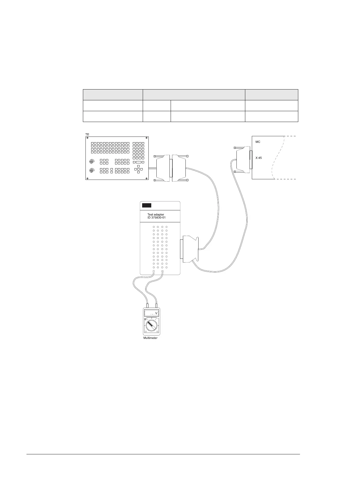
What to do if the motor encoder is loose on HEIDENHAIN ITNC 530?
- AallencarolineJul 26, 2025
If the motor encoder on your HEIDENHAIN Control Systems is loose, such as having a loose or defective coupling between the motor encoder housing and the motor housing, tighten or replace the coupling to ensure a secure connection.


