27 – 518 HEIDENHAIN Service Manual iTNC 530
X6:
PLC outputs
on the PL 510
Pin layout on the PLD 16-8 input/output module:
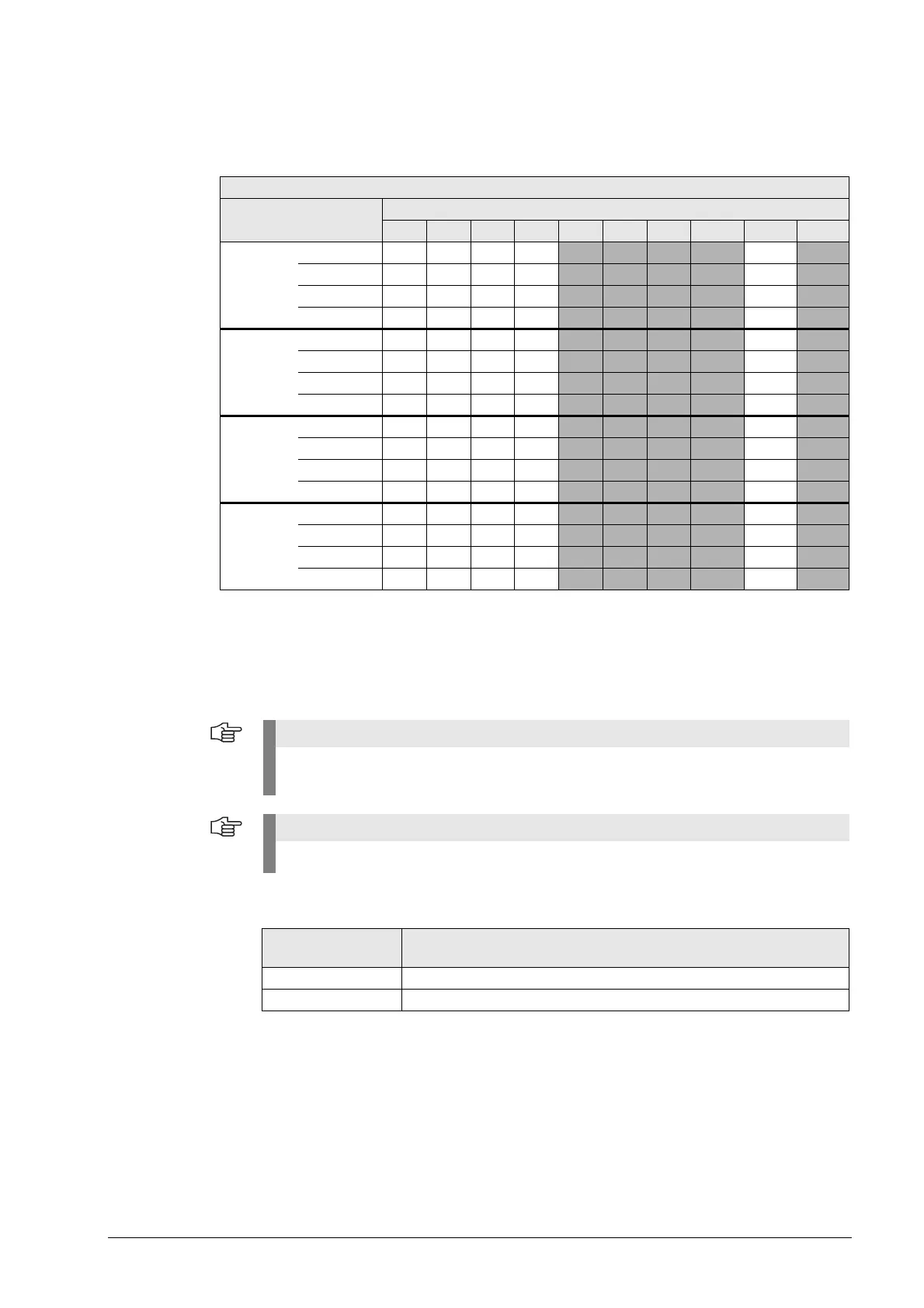
X6:
Power supply for
the PLC outputs on
PLD 16-8 input/
output module
Pin layout at X6 (power supply for PLC outputs):
X6
Pin layout Terminal
1 2 3 4 5 6 7 8 9 10
First
PL 510
Socket 1 O32 O33 O34 O35
O36 O37 O38 O39
a
+24 V
b
+24 V
c
Socket 2 O40 O41 O42 O43 O44 O45 O46 O47
a
+24 V
b
+24 V
c
Socket 3 O48 O49 O50 O51 O52 O53 O54 O55
a
+24 V
b
+24 V
c
Socket 4 O56 O57 O58 O59 O60 O61 O62 O63
a
+24 V
b
+24 V
c
Second
PL 510
Socket 1 O64 O65 O66 O67 O68 O69 O70 O71
a
+24 V
b
+24 V
c
Socket 2 O72 O73 O74 O75 O76 O77 O78 O79
a
+24 V
b
+24 V
c
Socket 3 O80 O81 O82 O83 O84 O85 O86 O87
a
+24 V
b
+24 V
c
Socket 4 O88 O89 O90 O91 O92 O93 O94 O95
a
+24 V
b
+24 V
c
Third
PL 510
Socket 1 O128 O129 O130 O131 O132 O133 O134 O135
a
+24 V
b
+24 V
c
Socket 2 O136 O137 O138 O139 O140 O141 O142 O143
a
+24 V
b
+24 V
c
Socket 3 O144 O145 O146 O147 O148 O149 O150 O151
a
+24 V
b
+24 V
c
Socket 4 O152 O153 O154 O155 O156 O157 O158 O159
a
+24 V
b
+24 V
c
Fourth
PL 510
Socket 1 O160 O161 O162 O163 O164 O165 O166 O167
a
+24 V
b
+24 V
c
Socket 2 O168 O169 O170 O171 O172 O173 O174 O175
a
+24 V
b
+24 V
c
Socket 3 O176 O177 O178 O179 O180 O181 O182 O183
a
+24 V
b
+24 V
c
Socket 4 O184 O185 O186 O187 O188 O189 O190 O191
a
+24 V
b
+24 V
c
a. The function of this terminal can be set with a sliding switch on the
rear side of the PLD 16-8 I/O modules:
Setting 1: Control-is-ready signal
Setting 2: PLC output
b. Group 1 (terminals 1 to 4)
c. Group 2 (terminals 5 to 8)
If you use only the outputs at X6 for a PLD 16-8 I/O unit (and no inputs), the 0-V connection
for supplying the electronics and for operating the LEDs must be established at X4 or X5.
The iTNC 530 cyclically monitors the PLC outputs of the PL 510 for a short-circuit.
Connecting
terminal
Pin layout
9 +24 Vdc (20.4 V to 28.8 V) for group 1 (terminal 1 - 4)
10 +24 Vdc (20.4 V to 28.8 V) for group 2 (terminal 5 - 8)

 Loading...


