OPERATOR'S STATION
1-112
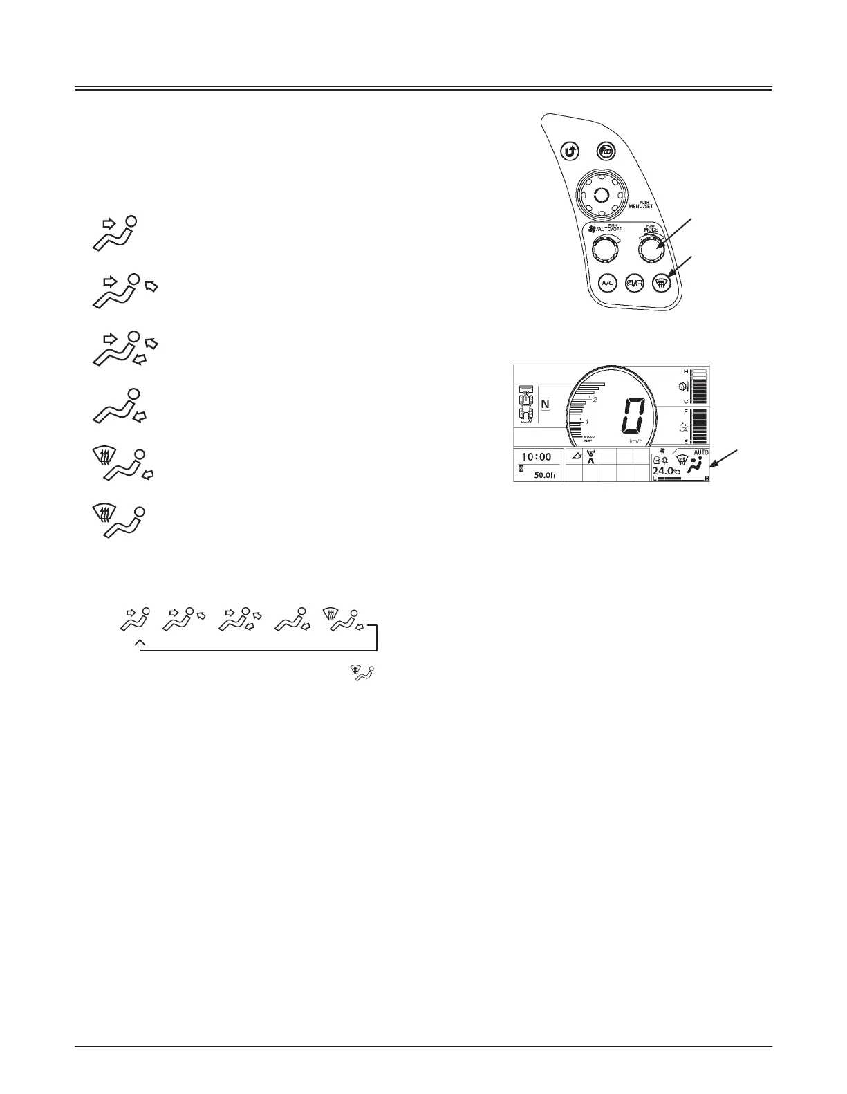
Controller Part Name and Function
Mode/Temperature Control Switch
Mode Switch (3)
Selects the air vent. The selected air vent is indicated on
monitor (1).
: Front Vent Mode
: Front/Rear Vent Mode
: Front/Rear/Foot Vent Mode
: Foot Vent Mode
: Foot/Defroster Vent Mode
: Defroster Vent Mode
Each time mode switch (3) is pressed, the vent location can
be changed in 6 stages as illustrated below.
AUTO
Press defroster switch (4) to change defroster vent
mode.
AUTO mode
The air vent location is automatically selected.
Temperature Control Switch (3):
Sets temperature in the cab.
Temperature in the cab can be set from 18.0 to 32.0 °C
(64 to 90 °F) by rotating temperature control switch (3).
Temperature can be set by 0.5 °C (32.9 °F) increments.
The set-temperature is displayed on monitor (1).
MNEC-01-006
3
4
1
MNEK-01-103EN

 Loading...