January 2007 95
Intel
®
855GME Chipset and Intel
®
6300ESB ICH Embedded Platform Design Guide
Compared to options 1-3, option 4 represents cost- and space-optimized decoupling solutions that
provide a competitive level of VRM performance and efficiency. Option 4 is the recommended
V
CC-CORE
decoupling solution for Intel Pentium M/Celeron M processor-based systems and offers
the best balance of performance, cost, and motherboard surface area requirements.
An example layout implementation of the recommended option 4 is illustrated in Figure 44,
Figure 45, Figure 46, and Figure 47. Figure 44 and Figure 45 show how the four, low-frequency SP
decoupling capacitors are placed on the secondary side and connected to the AF signal row of the
Intel Pentium M/Celeron M processor pins with a solid V
CC-CORE
flood area along with eight of
the mid-frequency 0805 ceramic mecoupling capacitors that are in between. To minimize the
inductance of the SP capacitor connection for the layout style shown, the sense resistors’ VRM
feed is on the positive terminal side of the SP capacitors. In this case each of the SP capacitors is
connected to two pairs of V
CC-CORE
/GND vias on the positive terminal. Refer to Figure 45 for
more details. When the VRM sense resistors connect from the negative side of the SP capacitors,
two pairs of V
CC-CORE
/GND vias are needed on both positive and negative terminals of the SP
capacitors.
Thirty-two 10 µF, 0805 capacitors are placed on the secondary side (Layer 8) while the remaining
three are placed on the primary side (Layer 1). Six of the 10-µF capacitors are placed outside the
socket outline with a 90-mil (or closer) pitch (as shown in Figure 45) and are divided evenly on
either side for the four 220 µF bulk capacitors (three to the left and three to the right of the SP
capacitors). Each of these six 0805 capacitors have a pair of V
CC-CORE
and GND stitching vias
next to both positive and negative terminals of the capacitors. The stitching vias connect to the
internal ground and V
CC-CORE
planes, respectively.
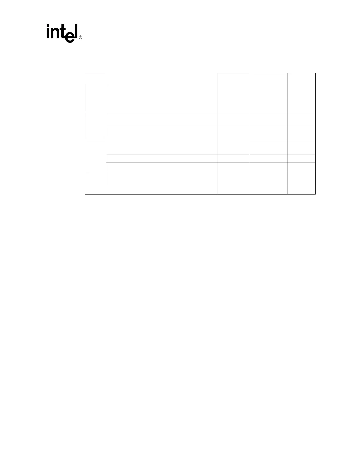
Table 21. Intel
®
Pentium
®
M/Celeron
®
M Processor V
CC-CORE
Decoupling Guidelines
Option Description Cap ESR ESL
1
Low-Frequency Decoupling (Polymer-Covered
Tantalum – POSCAP, Neocap, KO Cap)
12 x 150 µF 36 m
Ω (typ)/12 2.5 nH/12
Mid-Frequency Decoupling
(0612 MLCC, >= X5R)
15 x 2.2 µF 5 m
Ω (typ)/15 0.2 nH/15
2
Low-Frequency Decoupling
(1206 MLCC, >= X5R)
40 x 10 µF 5 m
Ω (typ)/40 1.2 nH/40
Mid-Frequency Decoupling
(0612 MLCC, >= X5R)
15 x 2.2 µF 5 m
Ω (typ)/15 0.2 nH/15
3
Low-Frequency Decoupling
(Polymer-Covered Aluminum – SP Cap, A0 Cap)
5 x 330µF 15m
Ω (max)/5 3.5 nH/5
Low-Frequency Decoupling (1206 MLCC, >= X5R) 25 x 10 µF 5 m
Ω (typ)/25 1.2 nH/25
Mid-Frequency Decoupling (0612 MLCC, >= X5R) 15 x 2.2 µF 5 m
Ω (typ)/15 0.2 nH/15
4
Low-Frequency Decoupling (Polymer-Covered
Aluminum – SP CAP, AO Cap)
4 x 220
μF12mΩ (max)/4 3.5 nH/4
Mid-Frequency Decoupling (0805 MLCC>= X5R) 35 x 10
μF5mΩ (typ)/35 0.6 nH/35
† Option 4 is to be used with small footprint (100 mm
2
or less) 0.36 µH ± 20% inductors.
 Loading...


