Memory Interface Routing
R
Intel
®
Pentium
®
4 Processor / Intel
®
850 Chipset Family Platform Design Guide 105
6.1.5 High-Speed CMOS Routing
Due to the synchronous requirements between RSL signals and high-speed CMOS signals, the
CMOS signals should be routed as part of the RSL channel. They must be impedance matched and
properly terminated (using a different termination scheme than the RSL signals). It is not necessary
to perform the length match calculation for high-speed CMOS signals. For PCB routing, the
mismatch between the CMOS signals (CMD, SCK) and the RSL signals should be kept as minimal
as possible.
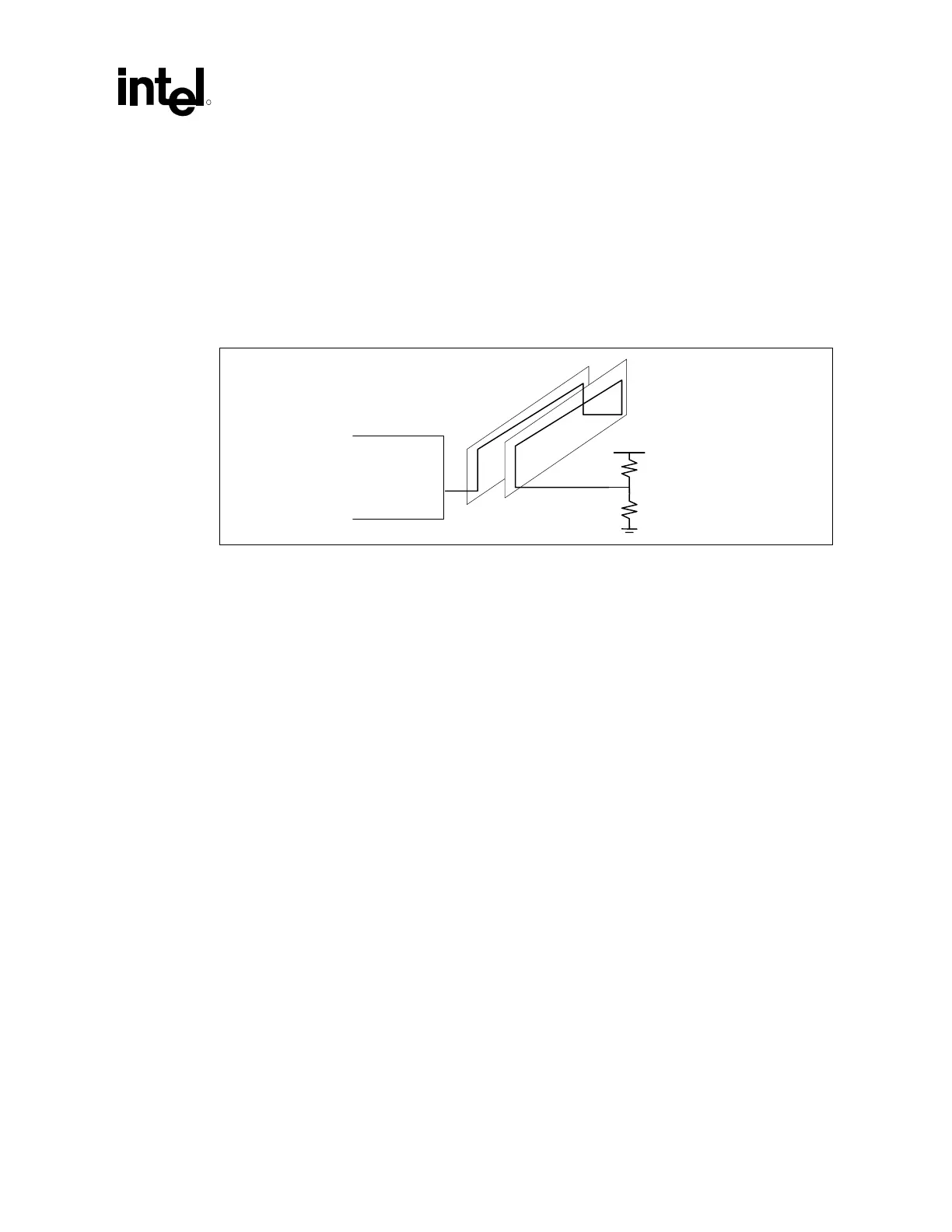
Figure 69. High-Speed CMOS RC Termination
MCH
Vterm
91ohm
39ohm
A CMOS voltage must be supplied to each RIMM connector. This CMOS voltage is used by the
RDRAM device CMOS interface. This voltage (Vcmos) must be 1.8 V, and the maximum load is
3 mA. Additionally, this voltage must be supplied during Suspend to RAM. Therefore, Vterm and
Vcmos cannot be generated from the same source. Due to the low power requirements of Vcmos,
it can be generated by a 36 / 100 Ω resistor divider from 2.5 V.
The high-speed CMOS signals require AC termination as shown Figure 69 with a 91 Ω pull-up
and 39 Ω pull-down resistors.
6.1.6 SIO Routing
The SIO signal is a bi-directional signal that operates at 1 MHz. This signal must be routed from
MCH to RIMM connector to RIMM connectors as documented below and shown in Figure 70.
• MCH SIO ball to the first RIMM connector’s SIN pin (RIMM #1 – Pin B36)
• First RIMM connector’s SOUT pin (RIMM connector #1 – Pin A36) to the second RIMM
connector’s SIN pin (RIMM connector #2 – Pin B36)
• Second RIMM connector’s SOUT pin (RIMM connector #1 – Pin A36) to terminating
resistor that is tied to GND
The SIO signal enters the first RIMM connector, propagates through all the devices (this signal is
buffered by each device) on the RIMM module and then exits the RIMM connector. A 2.2 kΩ–
10 kΩ terminating resistor is required on the last RIMM connector’s SOUT pin. This resistor
needs to be tied to GND. The SIO is routed with a 5 mil wide, 60 Ω trace.
 Loading...

