Memory Interface Routing
R
90 Intel
®
Pentium
®
4 Processor / Intel
®
850 Chipset Family Platform Design Guide
6.1 Rambus RDRAM* Device Routing Guidelines
The MCH has two Direct Rambus channels. The layout guidelines presented below are applicable
for each channel. One channel should be routed entirely microstrip (outer layers) or stripline (inner
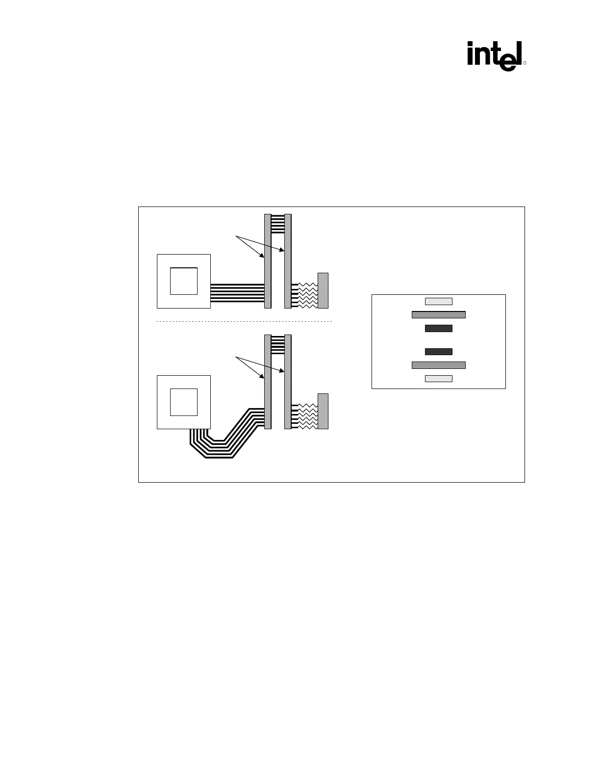
layers). Figure 56 illustrates an example routing topology for the MCH.
Figure 56. Intel
®
MCH Direct Rambus Channel Routing Example
RDRAM-CH_Route
MCH
RAC B
VTERM
RIMM
Connector
MCH
RAC A
VTERM
RIMM
Connector
Board Stackup
Channel A
Signal
Power
Channel B Signal
Channel B
Signal
Ground
Channel A Signal
The signals on the Direct Rambus channel are broken into three groups: Rambus Signaling Level
(RSL) signals, CMOS signals and clocking signals. The signal groups are documented in Table 21.
 Loading...

