I/O Controller Hub 2
R
Intel
®
Pentium
®
4 Processor / Intel
®
850 Chipset Family Platform Design Guide 177
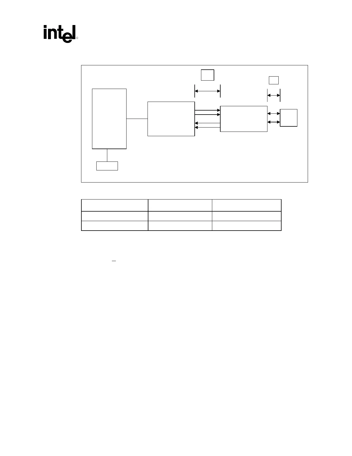
Figure 126. Critical Dimensions for Component Placement
82562ET
B
A
ICH2
EEPROM
Magnetics
Module
Line
RJ45
LAN_crit_dim_comp_place2
Table 41. Critical Dimension Values
Distance Priority Guideline
A 1 < 1 inch
B 2 < 1 inch
9.9.4.4.1 Distance from Magnetics Module to RJ45
The distance A in Figure 126 above should be given the highest priority in board layout. The
distance between the magnetics module and the RJ45 connector should be kept to less than one
inch of separation.
The following trace characteristics are important and should be observed:
• Differential Impedance: The differential impedance should be 100 ohms. The single ended
trace impedance will be approximately 50 Ω; however, the differential impedance can also be
affected by the spacing between the traces.
• Trace Symmetry: Differential pairs (such as TDP and TDN) should be routed with consistent
separation and with exactly the same lengths and physical dimensions (for example, width).
Caution: Asymmetric and unequal length traces in the differential pairs contribute to common mode noise.
This can degrade the receive circuit’s performance and contribute to radiated emissions from the
transmit circuit. If the 82562ET must be placed further than a couple of inches from the RJ45
connector, distance B can be sacrificed. Keeping the total distance between the 82562ET and
RJ45 will as short as possible should be a priority.
Note: Measured trace impedance for layout designs targeting 100 Ω often result in lower actual
impedance. OEMs should verify actual trace impedance and adjust their layout accordingly. If the
actual impedance is consistently low, a target of 105–110 Ω should compensate for second order
effects.