Layout Review Checklist
R
288 Intel
®
Pentium
®
4 Processor / Intel
®
850 Chipset Family Platform Design Guide
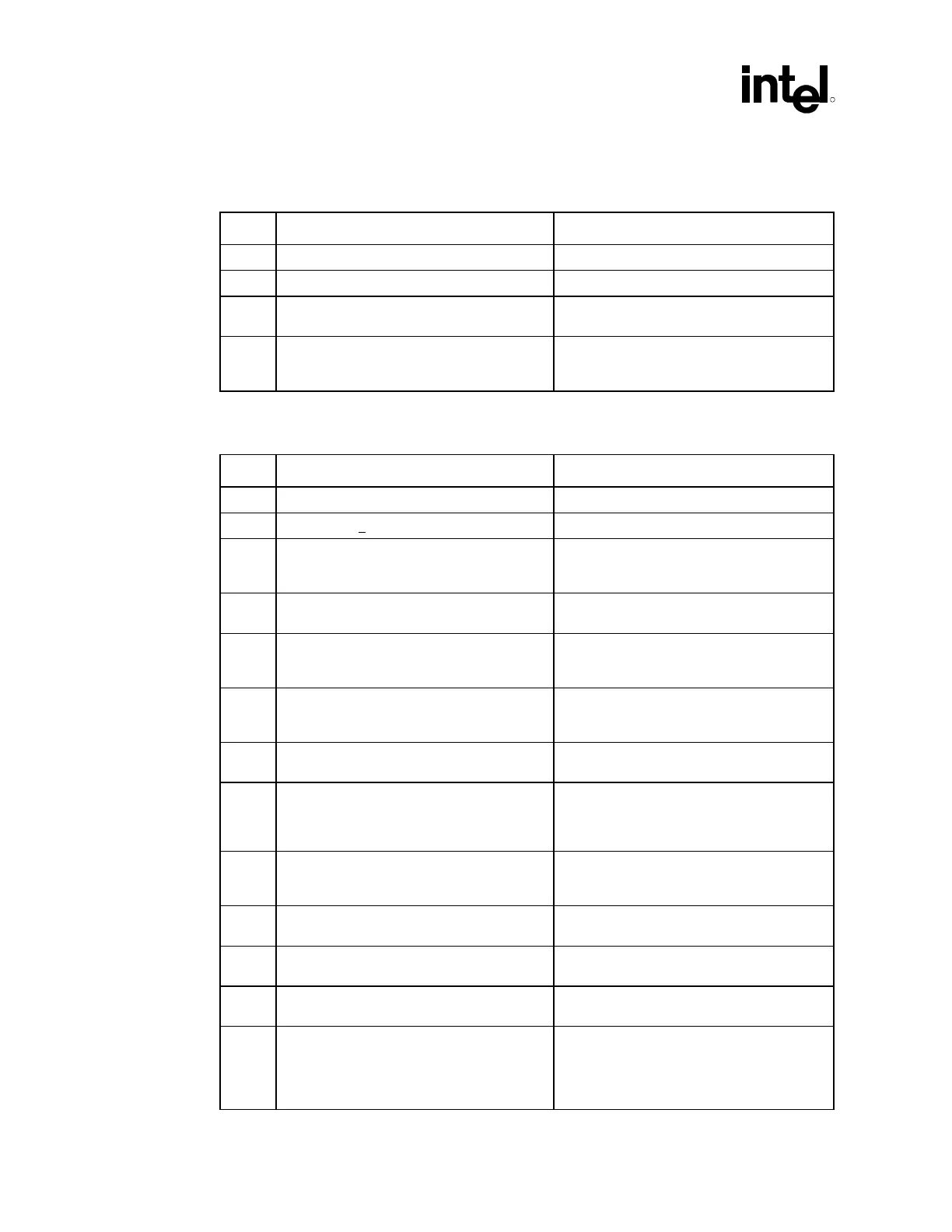
16.11 RTC
√ Recommendations Reason/Impact
• RTC LEAD length ≤ 0.25 inches Max • Refer to Section 9.8.3.
• Minimize capacitance between Xin and Xout • Refer to Section 9.8.3.
• Put GND plane underneath crystal
components
• Refer to Section 9.8.3.
• Do not route switching signals under the
external components (unless on other side
of board)
• Refer to Section 9.8.3.
16.12 LAN* Connect Interface
√ Recommendations Reason/Impact
• Stack-up: 5 mils wide, 10 mil spacing
• Z
O
= 60 Ω +15% • Signal integrity requirement.
• LAN Max Trace Length ICH2 to CNR:
L = 3 inches to 9 inches (0.5 inches to
3 inches on card)
• To meet timing requirements.
• Stubs due to R-pak CNR/LOM stuffing
option should not be present.
• To minimize inductance.
• Maximum Trace Lengths: ICH2 to
82562EH/ET/EM : L = 4.5 inches to
8.5 inches
• To meet timing requirements.
• Max mismatch between the length of a
clock trace and the length of any data trace
is 0.5 inches
• To meet timing and signal quality
requirements.
• Maintain constant symmetry and spacing
between the traces within a differential pair.
• To meet timing and signal quality
requirements.
• Keep the total length of each differential pair
under 4 inches.
• Issues found with traces longer than 4
inches : IEEE phy conformance failures,
excessive EMI and or degraded receive
BER.
• Do not route the transmit differential traces
closer than 70 mils to the receive
differential traces.
• To minimize cross-talk.
• Distance between differential traces and
any other signal line is 70 mils.
• To minimize cross-talk.
• Keep Max separation between differential
pairs to 7 mils.
• To meet timing and signal quality
requirements.
• Differential trace impedance should be
controlled to be ~100 ohms.
• To meet timing and signal quality
requirements.
• For high-speed signals, the number of
corners and vias should be kept to a
minimum. If a 90 degree bend is required, it
is recommended to use two 45 degree
bends.
• To meet timing and signal quality
requirements.
 Loading...

