Schematic Review Checklist
R
Intel
®
Pentium
®
4 Processor / Intel
®
850 Chipset Family Platform Design Guide 249
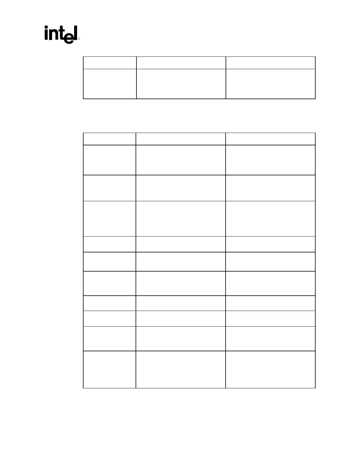
Checklist Items Recommendations Reason/Impact/Documentation
XTAL_in
XTAL_out
• Connect a 10 pF capacitor from
each signal to GND.
• Connect to 14.318 MHz crystal
oscillator.
• Capacitor values may vary slightly
from manufacturer to manufacturer.
15.3 Direct Rambus Clock Generator (DRCG1 and
DRCG2) Checklist
Checklist Items Recommendations Reason/Impact
VddIR • Connect to 3.3 V • Provides the voltage reference for
the Refclk clock output from CK00
clock generator
• Refer to Section 4.3.1.
Refclk • Connect Refclk pin of DRCG1 and
DRCG2 to 3VMRef and 3VMRef_b
outputs from the CK00 clock
generator.
ddP, VddC, VddO, • These are all 3.3 V voltage pins. Tie
directly to VCC3_3 supply.
• Place a 0.1 µF capacitor between
each pin and the VSS plane for
decoupling purposes.
GndP, GndI, GndC,
GndO
• Connect to GND. • These are all ground pins.
PclkM • Connect to HCLKOUT on MCH. • This is a host clock feedback input.
• Refer to Section 4.3.2.
SynclkN • Connect to RCLKOUT on MCH. • This is a Rambus clock feedback
input.
• Refer to Section 4.3.2.
VddIPD • Connect to 1.8 V power plane. • This is a voltage reference for PclkM
and SynclkN signals.
STOPB# • Terminate to 1.8 V power plane with
a 4.7 k
Ω resistor.
• This function is not used for Intel 850
chipset-based platform.
PWRDN# • Terminate to 3.3 V through a 4.7 kΩ
resistor.
• Connect to CK00 PWRDN# signal.
S1, S0 • Connect 1 kΩ ±5% series resistors
to S0 and S1 and connect signals
together. Connect joined signals
through a 4.7 k
Ω ±5% pull-down
resistor to GND and connect a
series resistor to a GPIO
• A low voltage (logic “0”) on S1 and
S0 places the DRCG* in normal
operation mode. The GPIO
connection allows software
adjustable mode control over CLK
and CLKB
 Loading...

