Intel® Pentium® 4 Processor in the 478-Pin Package Processor Power Distribution Guidelines
R
224 Intel
®
Pentium
®
4 Processor / Intel
®
850 Chipset Family Platform Design Guide
11.3.2 FMB2
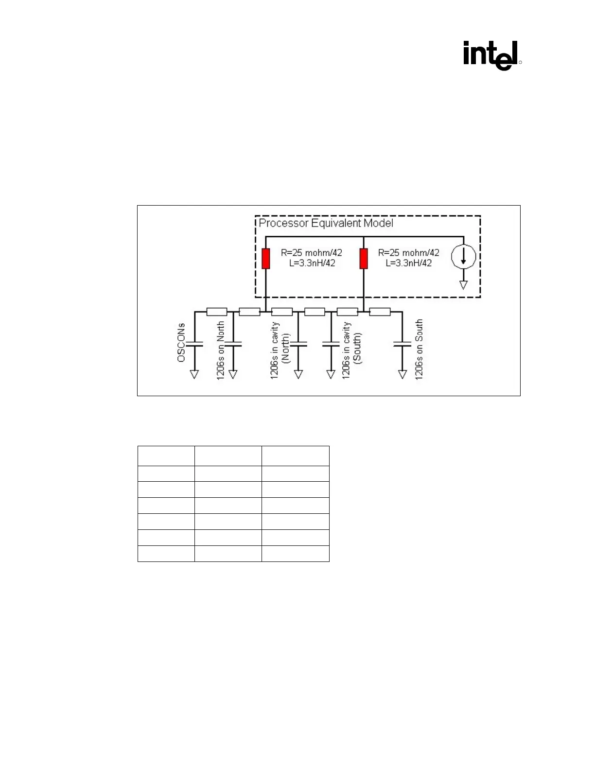
To completely model the system board, one must include the inductance and resistance that exists
in the cables, connectors, PCB planes, pins and body of components (such as resistors and
capacitors), processor socket, and the voltage regulator module. More detailed models showing
these effects are shown in Figure 167.
Figure 167. Detailed Power Distribution Model for Processor with Voltage Regulator on
System Board
Table 54. Intel
®
Pentium
®
4 Processor Power Delivery Model Parameters
Segment Resistance Inductance
L1 0.27 mΩ 80 pH
L2 0.33 mΩ 11.3 pH
L3 0.392 mΩ 104 pH
L4 0.196 mΩ 52 pH
L5 0.392 mΩ 104 pH
L6 0.64 mΩ 200 pH
 Loading...

