Layout Review Checklist
R
Intel
®
Pentium
®
4 Processor / Intel
®
850 Chipset Family Platform Design Guide 281
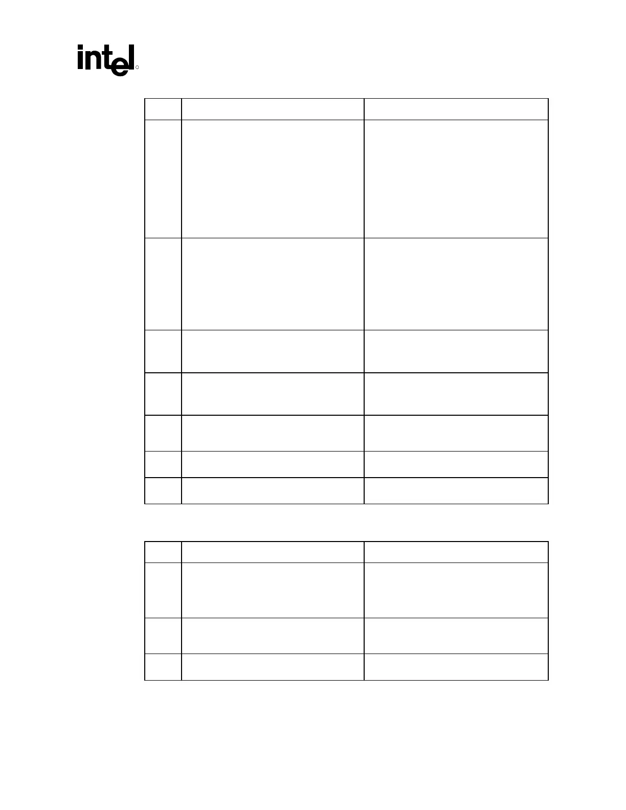
√ Recommendations Reason/Impact/Documentation
• CTM and CFM pairs routed differentially
should be routed:
22 mil ground trace
6 mil spacing
14 mil trace width (clock)
6 mil spacing
14 mil trace width (clock#)
6 mil spacing
22 mil ground trace.
• Refer to Section 4.3.3.1
• If CTM and CFM pairs routed single-ended,
route:
10 mil ground trace
6 mil spacing
18 mil wide clock trace
6 mil wide spacing
10 mil ground trace.
• Refer to Section 4.3.3.1.
• CFM and CTM pairs must be ground
referenced at all time.
• This recommendation ensures a proper
return current path.
• Refer to Section 4.3.3.2.
• CFM and CTM pairs must have additional
0.021 inches of trace for every 1 inch of
RSL trace.
• This added length is to compensate for the
clocks faster velocity.
• Refer to Section 4.3.3.2
• Ensure that each clock pair is length
matched within ±2 mils of the RSL channel
length. Exact matching is preferred.
• Refer to Section 4.3.3.1.
• Vias are placed in ground isolation traces
and ground reference every 1 inch.
• Refer to Section 4.3.3.1.
• When CTM/CTM# serpentine together, they
MUST maintain EXACTLY mils spacing
16.3.5 Rambus DRCG* Layout (Clean Power Supply)
√ Recommendations Reason/Impact
• 3.3 V DRCG* power flood on the top layer.
This should connect to each high frequency
(0.1
µF) capacitors are near the DRCG
power pins. One capacitor next to each
power pin.
• Refer to Section 4.3.5.
• 10 µF bulk tantalum capacitor near DRCG
connected directly to the 3.3 V DRC* power
flood on the top layer
• Refer to Section 4.3.5.
• Ferrite bead isolating DRCG power flood
from 3.3 V main power.
• Refer to Section 4.3.4.
 Loading...

