System Bus Routing
R
Intel
®
Pentium
®
4 Processor / Intel
®
850 Chipset Family Platform Design Guide 75
5.4.1.4 Topology 2B: Asynchronous GTL+ Signals Driven by Intel
®
ICH2
This signal (Open Drain; PWRGOOD) should adhere to the following routing and layout
recommendations. Figure 39 illustrates the recommended topology.
Table 18. Layout Recommendations for Miscellaneous Signals (Topology 2B)
Trace Zo Trace Spacing L1 L3 Rpu
60 Ω
7 mil 1–12" 3" max
300 Ω ±5%
Figure 39. Routing Illustration for PWRGOOD
Processor
Topo2b_pwrgd_Route
R
PU
VCC_CPU
ICH2
L1
L3
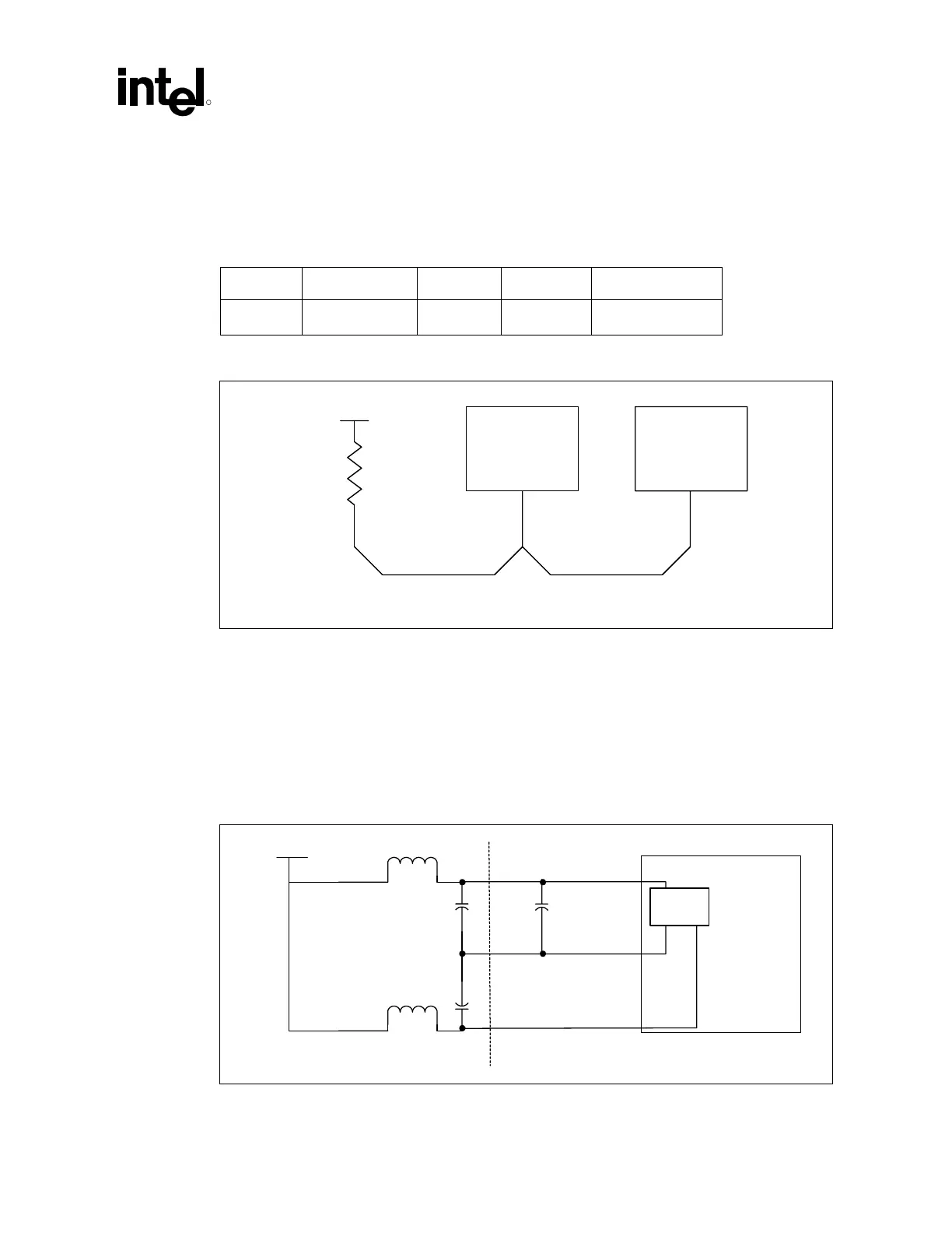
5.4.1.5 Topology 3: VCCIOPLL, VCCA and VSSA
VCCIOPLL and VCCA are isolated power for internal PLLs. It is critical that they have clean,
noiseless power on their input pins. Keep these signals away from noisy or high frequency signals.
Keep their traces as short as possible. Follow the recommendations in Figure 40 for layout
guidelines. VSSA should not be connected directly to ground on the system board. Further details
can be found in Section 11.4.
Figure 40. Routing Illustration for VCCIOPLL, VCCA and VSSA
VCC_CPU
VCCA
VSSA
VCCIOPLL
Processor
Core
PLLs
Mother
board
pkg
c2
1 uF
33 uF
33 uF
4.7 uH
4.7 uH
C
A
C
IO
VCCIOPLL-VCCA-VSSA_Routing
 Loading...

