Schematic Review Checklist
R
Intel
®
Pentium
®
4 Processor / Intel
®
850 Chipset Family Platform Design Guide 259
15.7 Intel
®
ICH2 Checklist
15.7.1 PCI Interface
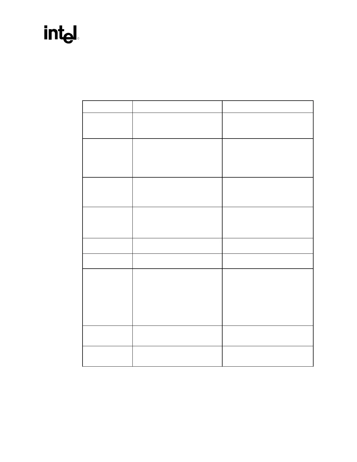
Checklist Items Recommendations Reason/Impact
FYI • Inputs to the ICH2 must not be left
floating.
• Many GPIO signals are fixed inputs
that must be pulled up to different
sources. See Section 15.7.7 for
recommendations
PERR# SERR#
PLOCK# STOP#
DEVSEL# TRDY#
IRDY# FRAME#
REQ#[0:4]
GPIO[0:1] THRM#
• These signals require a pull-up
resistor. Recommend an 8.2 k
Ω pull-
up resistor to VCC3_3 or a 2.7 k
Ω
pull-up resistor to VCC5.
• See PCI 2.2 Component Specification
Pull-up recommendations for
VCC3_3 and VCC5.
PCIRST# • The PCIRST# signal should be
buffered to form the IDERST# signal
• 33 Ω series resistor to IDE
connectors.
• Improves signal integrity
PCIGNT# • No external pull-up resistors are
required on PCI GNT signals.
However, if external pull-up resistors
are implemented, they must be
pulled up to VCC3_3.
• These signals are actively driven by
the ICH2
PME# • No extra pull-up resistors • These signals have integrated pull-
ups of 9 k
Ω ±3 kΩ.
SERIRQ • External weak (8.2 kΩ) pull-up
resistor to VCC3_3 is recommended.
• Open drain signal
GNT[A]# /GPIO[16],
GNT[B]/ GNT[5]#/
GPIO[17]
• No extra pull-up needed • These signals have integrated pull-
ups of 24 k
Ω.
• GNT[A] has an added strap function
of “top block swap”. The signal is
sampled on the rising edge of
PWROK. Default value is high or
disabled due to pull-up. A Jumper to
a pull-down resistor can be added to
manually enable the function.
GPIx • Connect GPI from processor pin
BSEL0/CK00 pin SEL100/133 to
ICH2 or SIO
• Used to forward system bus
frequency to BIOS for 100 MHz or
133 MHz system bus operation
GPOx • Route two GPO’s from ICH2 or SIO
to RDRAM Device Clock Generator
pins Mult0, Mult1
• Allows BIOS to set the 4:3 Host-to-
RDRAM devicefrequency ratio for
133 MHz system bus operation
 Loading...

