I/O Controller Hub 2
R
Intel
®
Pentium
®
4 Processor / Intel
®
850 Chipset Family Platform Design Guide 139
9.2 Communication and Networking Riser (CNR)
The Communication and Networking Riser (CNR) Specification defines a hardware scalable
Original Equipment Manufacturer (OEM) system board riser and interface. This interface supports
multi-channel audio, V.90 analog modem, phone-line based networking, and 10/100 Ethernet
based networking. The CNR specification defines the interface, which should be configured prior
to shipment of the system. Standard I/O expansion slots, such as those supported by the PCI bus
architecture, are intended to continue serving as the upgrade medium.
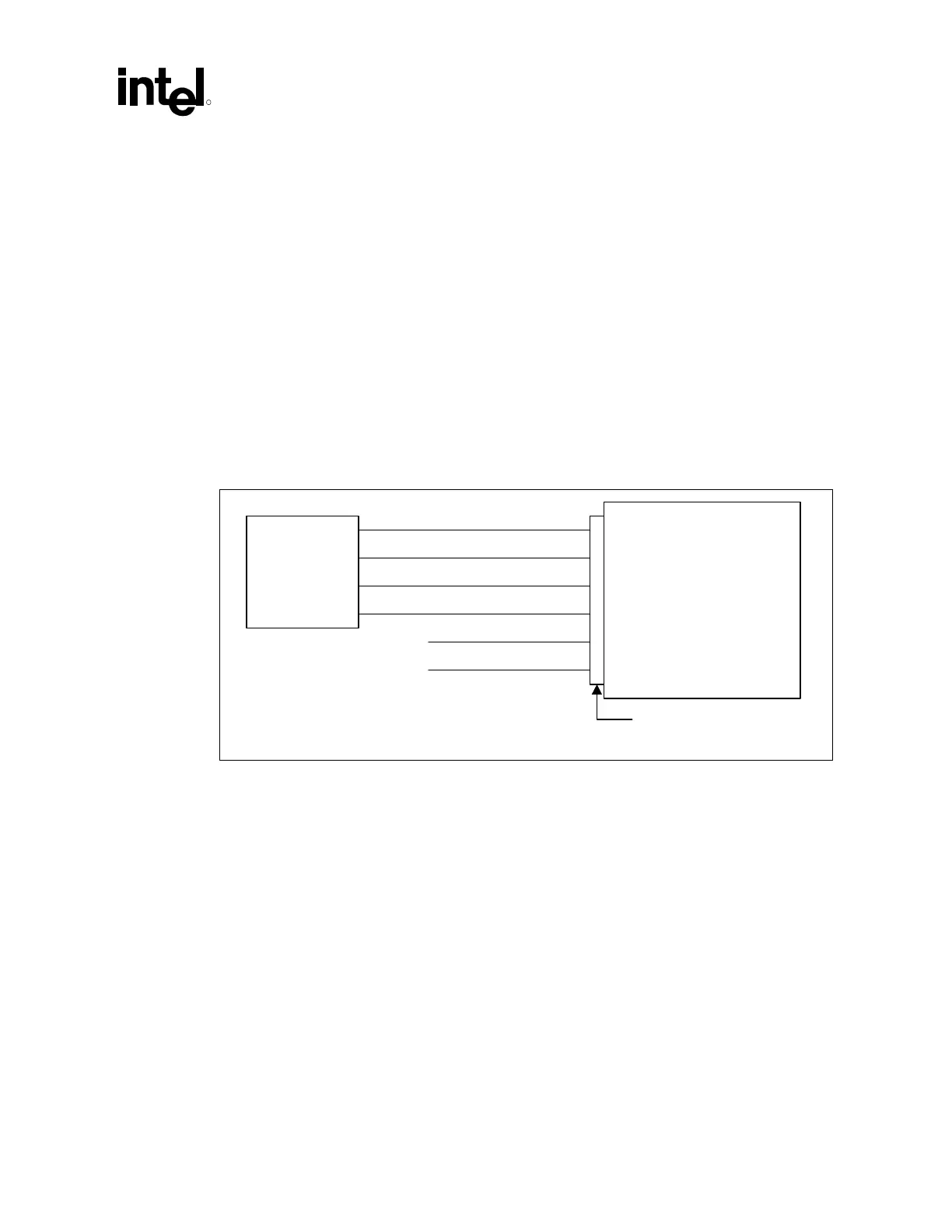
Figure 91 indicates the interface for the CNR connector. Refer to the appropriate section of this
document for the corresponding design and layout guidelines. The Platform LAN Connection
(PLC) can either be a 82562ET, 82562EM, or 82562EH component. It is required that the CNR
A0–A2 pins be set to a unique address, so that the CNR EEPROM can be accessed. Refer to the
CNR specification for additional information.
Figure 91. CNR Interface
AC '97 Interface
LAN Interface
USB
SMBus
Power
Reserved
CNR_interface
CNR Connector
Communication and
Networking Riser
(up to 2 AC '97 codecs
and 1 PLC device)
Core logic
controller
9.2.1 CNR Placement
Refer to the Communication and Network Riser Specification, Revision 1.0 for CNR placement.
 Loading...

