I/O Controller Hub 2
R
176 Intel
®
Pentium
®
4 Processor / Intel
®
850 Chipset Family Platform Design Guide
9.9.4.2 Crystals and Oscillators
To minimize the effects of EMI, clock sources should not be placed near I/O ports or board edges.
Radiation from these devices may be coupled onto the I/O ports or out of the system chassis.
Crystals should also be kept away from the Ethernet magnetics module to prevent interference of
communication. The retaining straps of the crystal (if they should exist) should be grounded to
prevent possibility radiation from the crystal case and the crystal should lay flat against the PC
board to provide better coupling of the electromagnetic fields to the board.
For a noise free and stable operation, place the crystal and associated discretes as close as possible
to the 82562ET or 82562EM, keeping the trace length as short as possible and do not route any
noisy signals in this area.
9.9.4.3 Intel
®
82562ET / 82562EM Termination Resistors
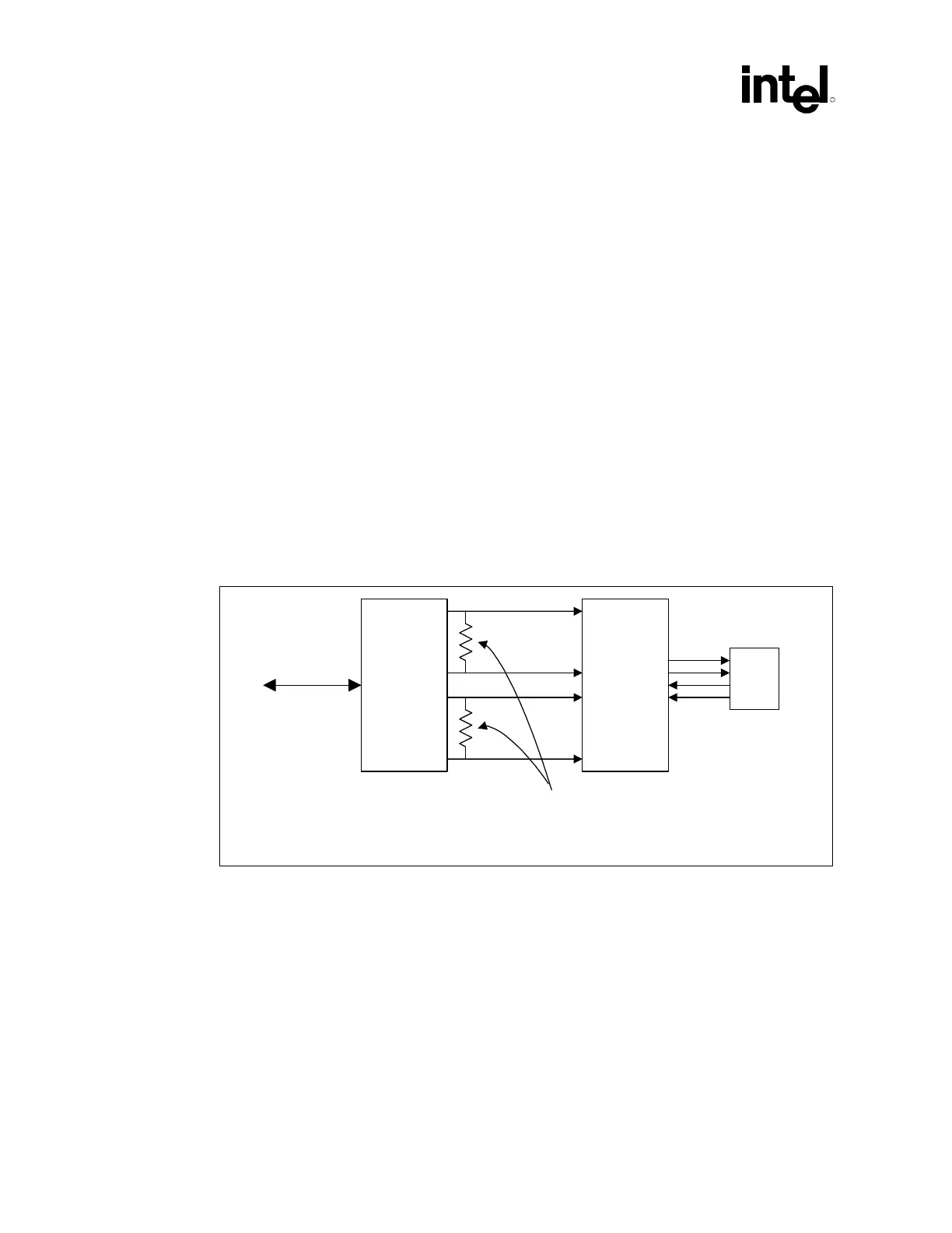
The 100 Ω 1% resistor used to terminate the differential transmit pairs (TDP/TDN) and the
120 Ω 1% receive differential pairs (RDP/RDN) should be placed as close to the LAN connect
component (82562ET or 82562EM) as possible. This is due to the fact these resistors are
terminating the entire impedance that is seen at the termination source (i.e., 82562ET), including
the wire impedance reflected through the transformer.
Figure 125. Intel
®
82562ET/ 82562EM Termination
LAN_82562ET-82562EM_term
82562ET
Magnetics
module
RJ45
Place termination resistors as
close as possible to 82562ET.
LAN connect
interface
9.9.4.4 Critical Dimensions
There are two dimensions to consider during layout. Distance ‘B’ from the line RJ45 connector to
the magnetics module and distance ‘A’ from the 82562ET or 82562EM to the magnetics module
(See Figure 126).
 Loading...

